Home
Panasonic
Digital Camera
DMC-TZ7EB
Page 38
Panasonic DMC-TZ7EB - Page 38
63 pages
Manual
Save Page as PDF
To Next Page
To Next Page
To Previous Page
To Previous Page
Loading...
38
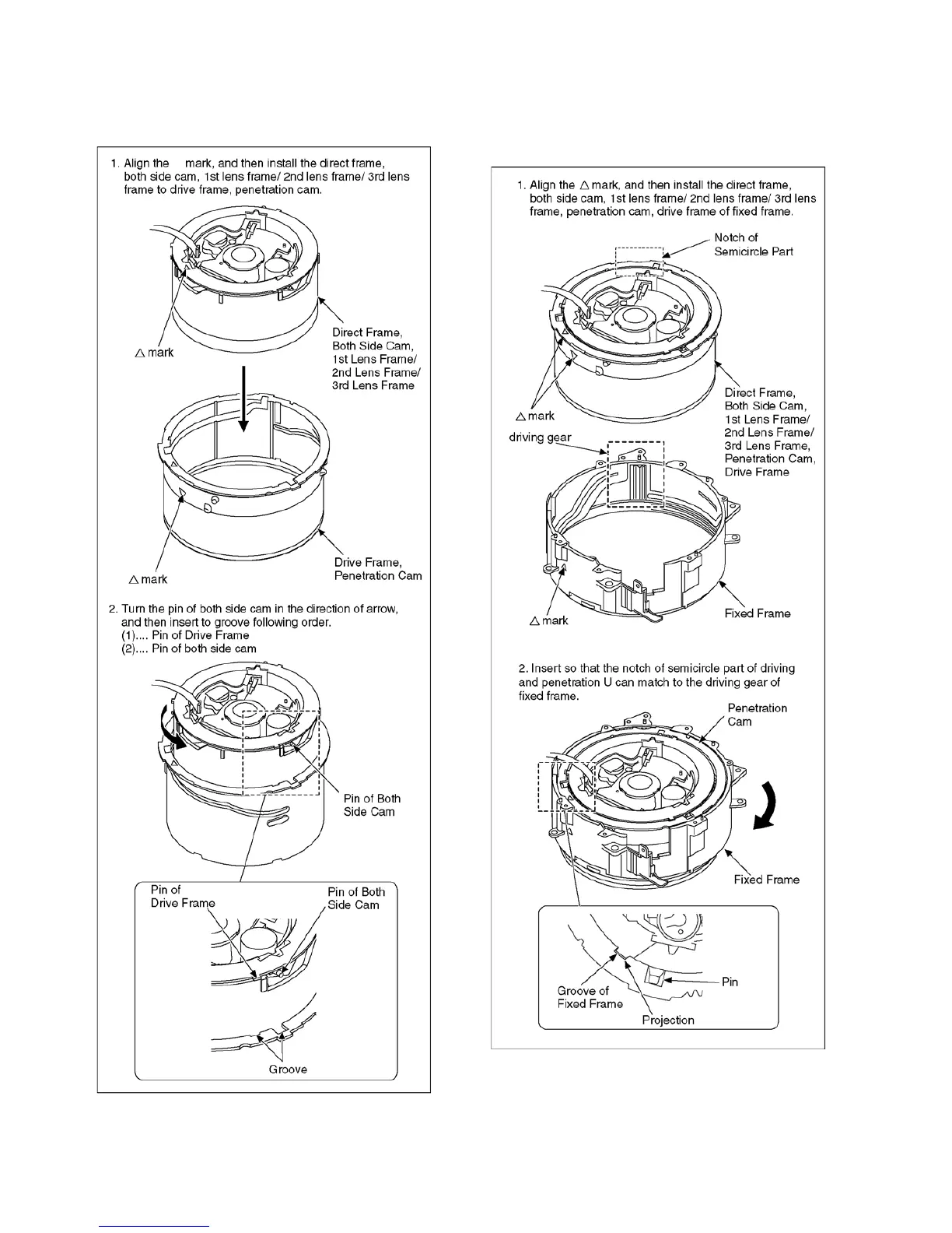
8.5.5.
Assembly for the Direct Frame,
Both Side Cam a
nd 1st Lens Frame/
2nd Lens Frame/3rd Lens Frame
8.5.6.
Assembly for the Direct Frame,
Both Side Cam an
d 1st Lens Frame/
2nd Lens Frame/3rd Lens Frame,
Penetration Cam and Drive Frame
37
39
Table of Contents
Main Page
Table of Contents
2
1 Safety Precautions
3
General Guidelines
3
Leakage Current Cold Check
3
Leakage Current Hot Check (See Figure 1)
3
How to Discharge the Capacitor on Flash Top PCB
4
2 Warning
5
Prevention of Electrostatic Discharge (ESD) to Electrostatic Sensitive (ES) Devices
5
How to Recycle the Lithium Ion Battery (U.S. Only)
5
Caution for AC Cord (for EB/GC
6
How to Replace the Lithium Battery
7
3 Service Navigation
8
Introduction
8
General Description about Lead Free Solder (Pbf)
8
Important Notice 1:(Other than U.S.A. and Canadian Market)
8
How to Define the Model Suffix (NTSC or PAL Model)
9
Initial Settings
11
4 Specifications
13
5 Location of Controls and Components
15
6 Service Mode
17
Error Code Memory Function
17
ICS (Indication of Additional Camera Settings When Picture was Taken) Function
21
7 Service Fixture & Tools
23
Service Fixture and Tools
23
When Replacing the Main PCB
23
Service Position
24
8 Disassembly and Assembly Instructions
25
Disassembly Flow Chart
25
PCB Location
25
Disassembly Procedure
26
Disassembly Procedure for the Lens
32
Assembly Procedure for Lens
36
Removal of the CCD Unit
39
Removal of the Zoom Motor Unit
40
Removal of the Focus Motor Unit
40
The Applyment of Grease Method
41
9 Measurements and Adjustments
42
Matrix Chart for Replaced Part and Necessary Adjustment
42
10 Maintenance
43
Cleaning Lens, Viewfinder and LCD Panel
43
Service Manual
44
S2. Voltage Chart
45
S2.1. Top Operation P.C.B
45
S2.2. Flash P.C.B
45
S3. Block Diagram
46
S3.1. Overall Block Diagram
46
S4. Schematic Diagram
47
S4.1. Interconnection Diagram
47
S4.2. Top Operation Schematic Diagram
48
S4.3. Top MIC Schematic Diagram
49
S4.4. Flash Schematic Diagram
50
S4.5. CCD Flex Schematic Diagram
51
S4.6. Lens Flex Schematic Diagram
52
S5. Print Circuit Board
53
S5.1. Top Operation P.C.B
53
S5.2. Flash P.C.B
54
S5.3. CCD Flex P.C.B
55
S5.4. Lens Flex P.C.B
56
S6. Replacement Parts List
58
S7. Exploded View
62
S7.1. Frame and Casing Section
62
S7.2. Packing Parts and Accessories Section
63
Related product manuals
Panasonic DMC-TZ70
305 pages
Panasonic DMC-TZ71
305 pages
Panasonic LUMIX DMC-TZ7
64 pages
Panasonic Lumix DMC-TZ70
305 pages
Panasonic Lumix DMC-TZ71
305 pages
Panasonic Lumix DMC-TZ70GN
305 pages
Panasonic DMC-TZ5
52 pages
Panasonic DMC-TZ80
64 pages
Panasonic DMC-TZ60
2 pages
Panasonic DMC-TZ101
64 pages
Panasonic Lumix DMC-TZ5
116 pages
Panasonic Lumix DMC-TZ3
108 pages