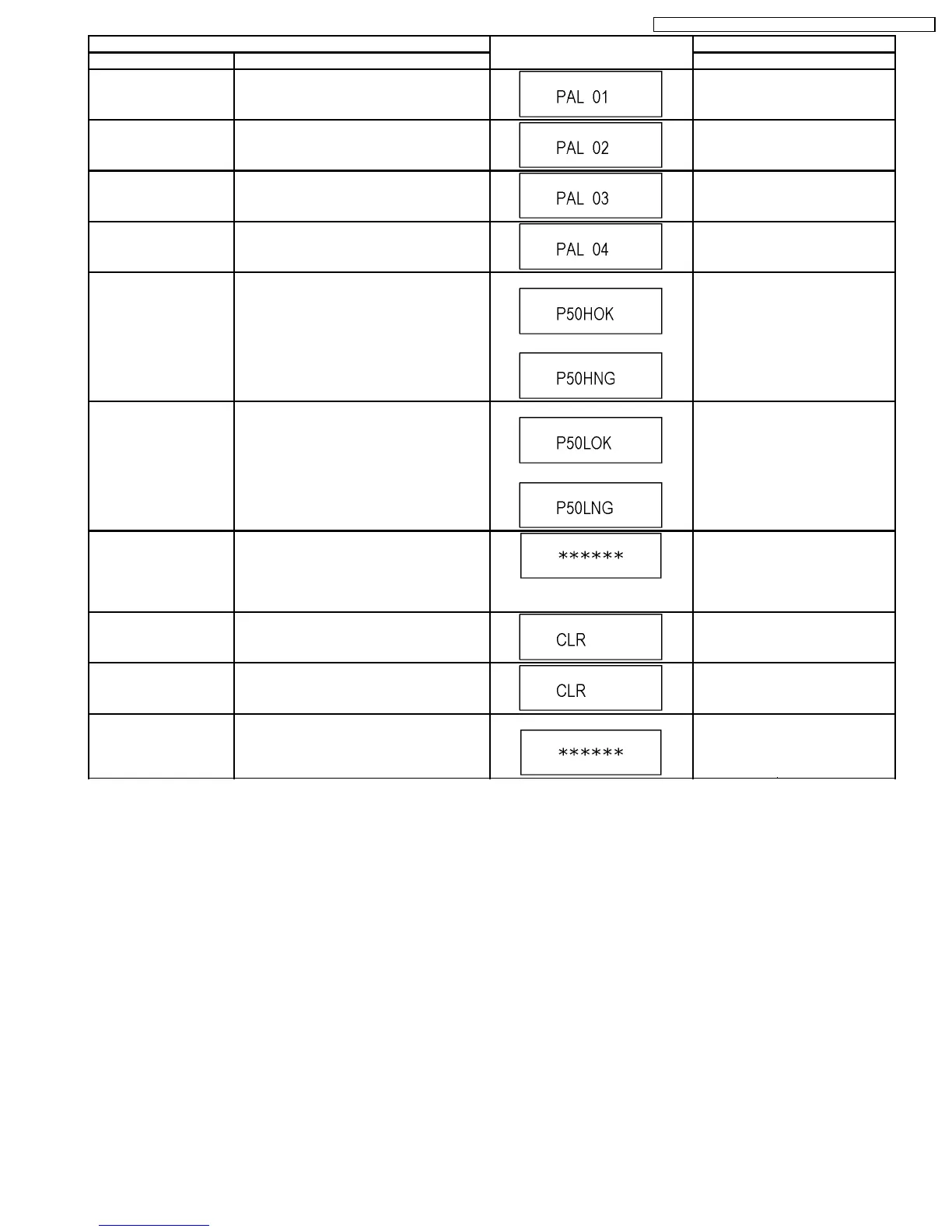
Item FL display Key operation
Mode name Description (Remote controller key)
AV4(V)/AV1(RGB) I/O
Setting
Set input to AV4 (V) and set output to AV1
(RGB) for I/O checking
Press [8] [0] in service mode.
AV2(Y/C)/AV1(V) I/O
Setting
Set input to AV2 (Y/C) and set output to AV1
(V) for I/O checking
Press [8] [1] in service mode.
AV2(V)/AV1(Y/C) I/O
Setting
Set input to AV2 (V) and set output to AV1
(Y/C) for I/O checking
Press [8] [2] in service mode.
AV2(RGB)/AV1(V) I/O
Setting
Set input to AV2 (RGB) and set output to AV1
(V) for I/O checking
Press [8] [3] in service mode.
P50(H) Output Timer Microprocessor IC7501-76 output High
signal for AV1-pin 10 passing through inverter
(approx. 0V DC at AV1-pin 10).
When OK.
When NG.
Press [8] [4] in service mode.
P50(L) Output Timer Microprocessor IC7501-76 output Low
signal for AV1-pin 10 passing through inverter
(approx. 4.4V DC at AV1-pin 10).
When OK.
When NG.
Press [8] [5] in service mode.
Tray OPEN/CLOSE Test The RAM drive tray is opened and closed
repeatedly.
“*” is number of open/close cycle
times.
Press [9] [1] in service mode
*When releasing this mode, press
the [POWER] button of Remote
Controller more than 10 seconds.
Error code initialization Initialization of the last error code held by
timer (Write in F00)
Press [9] [8] in service mode.
Initialize Service Last Drive Error, Error history and Error
Codes stored on the unit are initialized to
factory setting.
Press [9] [9] in service mode.
Finishing service mode Release Service Mode. Display in STOP (E-E) mode. Press power button on the front
panel or Remote controller in
service mode.
29
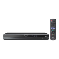
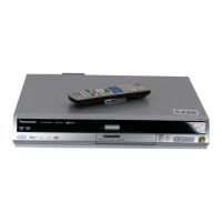
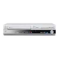
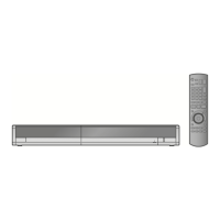
DMR-EH65EE / DMR-EH65GC / DMR-EH65GCS / DMR-EH65GN
 Loading...