9
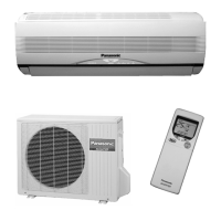
Minimum indoor volume & floor area relative to the amount of
refrigerant are roughly as given in the following table.
Min. indoor floor area
(when the ceiling is 2.7 m high)
40.5
54.0
27.0
13.5
0.0
20100 30 40 60 70 80 90 10050
67.5
81.0
94.5
108.0
121.5
135.0
148.5
162.0
175.5
189.0
202.5
216.0
229.5
243.0
256.0
270.0
m
2
m
3
15
10
5
0
20
25
30
35
40
45
50
55
60
65
70
75
80
85
90
95
100
105
110
115
120
125
283.5
297.0
310.5
324.0
337.5
kg
Min. indoor volume
Total amount of refrigerant
CAUTION
Pay special attention to any location, such as a basement,
etc. where leaking refrigerant can accumlate, since
refrigerant gas is heavier than air.
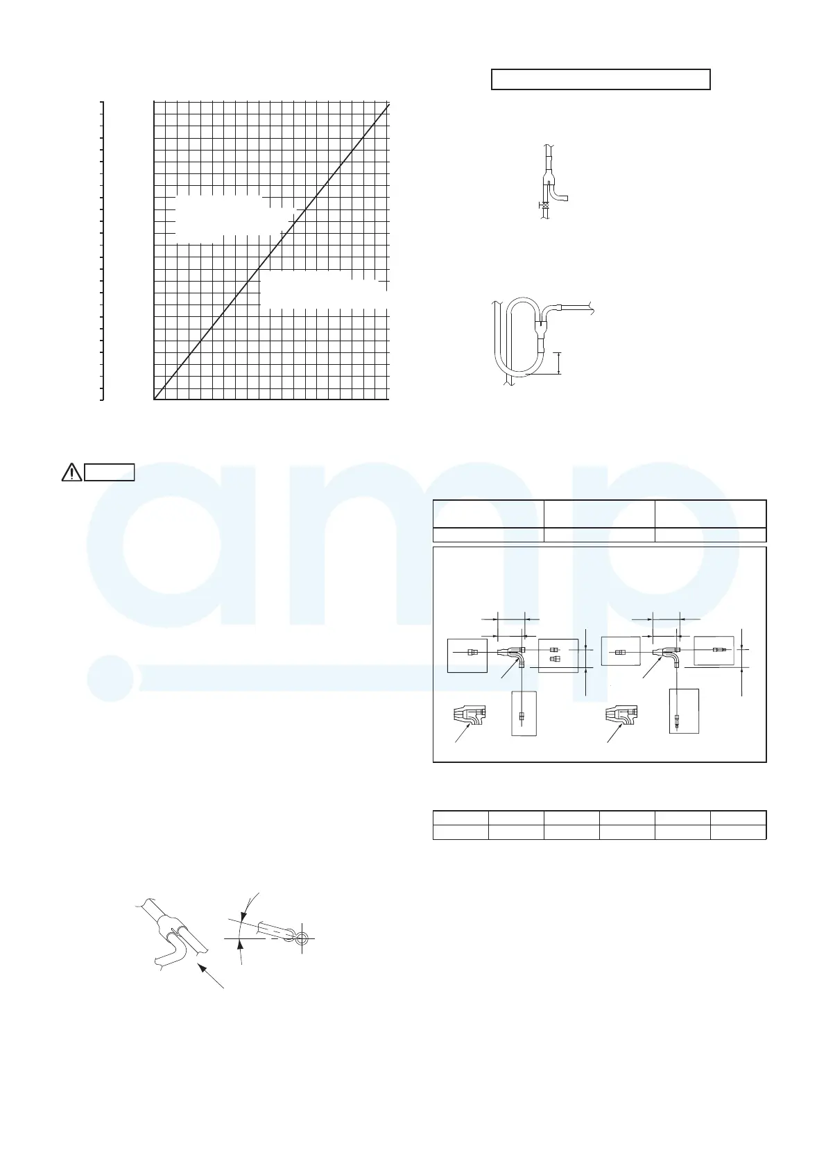
1-11. Installing Distribution Joint
(1) Refer to “HOW TO ATTACH DISTRIBUTION JOINT”
enclosed with the optional distribution joint kit
(CZ-P160BK2).
(2) In order to prevent accumulation of refrigerant oil in
stopped units, if the main tubing is horizontal then each
branch tubing length should be at an angle that is greater
than horizontal. If the main tubing is vertical, provide a
raised starting portion for each branch.
(3) If there are height differences between indoor units or if
branch tubing that follows a distribution joint is connected
to only 1 unit, a trap or ball valve (field supply) must be
added to that distribution joint. (When adding the ball
valve, locate it within 40 cm of the distribution joint.)
If a trap or ball valve (field supply) is not added, do not
operate the system before repairs to a malfunctioning unit
are completed. (The refrigerant oil sent through the tubing to
the malfunctioning unit will accumulate and may damage the
compressor.)
B
B
A
15 to 30º
Horizontal
line
View as seen from
arrow
Arrow view
Tube branching methods (horizontal use)
Types of vertical trap specifications
(When using ball valve (field supply))
Indoor unit (more than 2 units)
(If only 1 unit is connected, a ball
valve is also needed on this side.)
Ball valve
(BV: field supply)
Indoor unit (1)
(When not using ball valve)
Main tubing
Horizontal
Indoor unit
(Each unit is
connected to
tubing that is either
level or is directed
downward.)
Branch tubing is
directed upward.
Indoor unit is directed downward
Main tubing
More than
20 cm
1-12. Optional Distribution Joint Kit
See the installation instructions packaged with the distribution
joint kit for the installation procedure.
Table 1-11
Model name
Cooling capacity
after distribution
Remarks
CZ-P160BK2 22.4 kW or less For indoor unit
CZ-P160BK2
Use: For indoor unit (Capacity after distribution joint is 22.4 kW or less.)
B
B
B
C
A
C
A
110
97
72
C
C
C
E
D
DE
D
72
110
97
Table 1-12 Size of connection point on each part
(shown are inside diameters of tubing)
Size Part A Part B Part C Part D Part E
mm ø19.05 ø15.88 ø12.7 ø9.52 ø6.35
Unit: mm
Example
Gas tube
Liquid tube
Distribution joint
Insulation
Distribution
joint
Insulation
Range above the
density limit of 0.3 kg/m³
(Countermeasures needed)
Range below the
density limit of 0.3 kg/m³
(Countermeasures not
needed)
MiniVRFeng.indd9MiniVRFeng.indd9 2011/08/2613:45:122011/08/2613:45:12
www.ampair.co.uk | sales@ampair.co.uk
 Loading...