27
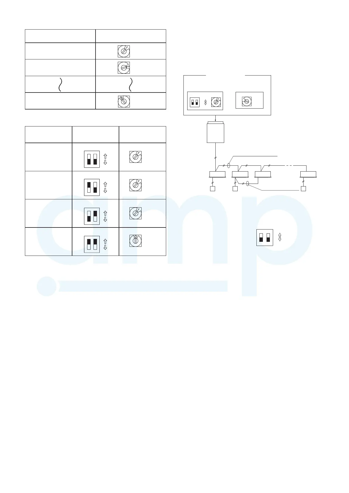
● Examples of the No. of indoor units settings
No. of indoor units
Indoor unit setting (S004)
(Rotary switch, gray)
1 unit (factory setting)
set to 1
2 units
set to 2
9 units
set to 9
● Examples of refrigerant circuit (R.C.) address settings
(required when link wiring is used)
System address
No.
System address
(S003)
(2P DIP switch, black)
System address
(S002)
(Rotary switch, yellow)
System 1 (factory setting)
12
set to 1
System 11
12
set to 1
System 21
12
set to 1
System 30
12
set to 0
Both OFF
1 ON
2 ON
1&2 ON
ON
OFF
ON
OFF
ON
OFF
ON
OFF
ON
ON
ON
ON
7-4. Auto Address Setting
Basic wiring diagram: Example (1)
•
If link wiring is not used
(The inter-unit control wires are not connected to multiple
refrigerant systems.)
Indoor unit addresses can be set without operating the
compressors.
(S004)
1
2
(S003) (S002)
1-1 1-2 1-3 1-8
8
Fig. 7-6
(1) Automatic Address Setting from the Outdoor Unit
1
On the outdoor unit control PCB, check that the system
address rotary switch (S002) is set to “1” and that the DIP
switch (S003) is set to “0”.
ON
ON
OFF
1
2
(These are the settings at the time of factory shipment.)
2
To set the number of indoor units that are connected to the
outdoor unit to 8 on the outdoor unit control PCB, set the
No. of indoor units rotary switch (S004) to “8”.
3
Turn ON the power to the indoor and outdoor units.
4
On the outdoor unit control PCB, short-circuit the automatic
address pin (CN-A.ADD) for 1 second or longer, then
release it.
↓
(Communication for automatic address setting begins.)
↓
*
To cancel, again short-circuit the automatic
address pin (CN-A.ADD) for 1 second or
longer, then pull it out.
The LED that indicates that automatic address
setting is in progress turns OFF and the
process is stopped.
(Automatic address setting is completed when LEDs 1 and
2 on the outdoor unit control PCB turn OFF.)
↓
5
Operation from the remote controllers is now possible.
*
To perform automatic address setting from the remote
controller, perform steps 1 to 3, then use the remote
controller and complete automatic address setting.
Refer to “Automatic Address Setting from the Remote
Controller.”
No. 1 unit settings
System address
(system 1 setting)
No. of indoor units
(8 units setting)
Outdoor
Unit
Unit
No. 1
Indoor Unit
Remote
controller
Inter-unit control wiring
Remote controller
communication wiring
ON
OFF
ON
MiniVRFeng.indd27MiniVRFeng.indd27 2011/08/2613:45:232011/08/2613:45:23
www.ampair.co.uk | sales@ampair.co.uk
 Loading...