8
1-7. Additional Refrigerant Charge
Additional refrigerant charge amount is calculated from the
liquid tubing total length as follows.
Table 1-7 Amount of Refrigerant Charge Per Meter,
According to Liquid Tubing Size
Liquid tubing size Amount of refrigerant
charge/m (g/m)
ø6.35 26
ø9.52 56
Required amount of charge
=
(Amount of refrigerant charge per meter of each size of liquid tube
× its tube length) + (...) + (...)
* Always charge accurately using a scale for weighing.
Table 1-8 Refrigerant Charge Amount at Shipment (for
outdoor unit)
4 hp 5 hp 6 hp
3.5 3.5 3.5
Unit: kg, hp = horsepower
1-8. System Limitations
Table 1-9 System Limitations
Outdoor units 4 hp 5 hp 6 hp
Number of max.
connectable indoor units
689
Max. allowable indoor/
outdoor capacity ratio
50 – 130%
hp = horsepower
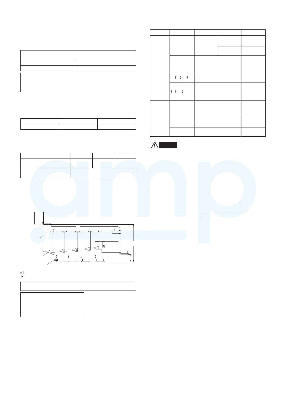
1-9. Tubing Length
Select the installation location so that the length and size of
refrigerant tubing are within the allowable range shown in the
figure below.
H1
H2
LA
L1
L2
LDLCLB
L3
n
1
2
3
n-1
Note: Do not use commercially available T-joints for the liquid tubing.
* Be sure to use special R410A
distribution joints (CZ-P160BK2 :
purchased separately) for outdoor
unit connections and tubing
branches.
R410A distribution joint
CZ-P160BK2 (for indoor unit)
Table 1-10 Ranges that Apply to Refrigerant Tubing Lengths
and to Differences in Installation Heights
Items Marks Contents Length (m)
Allowable
tubing
length
L1
Max. tubing
length
Actual
length
≤ 120
Equivalent
length
≤ 140
Δ
L (L2 – L3)
Difference between max.
length and min. length
from the No.1 distribution
joint
≤ 40
1
,
2
...
n
Max. length of each
distribution tube
≤ 30
1
,
2
...
n-1
+L1
Total max. tubing length
including length of each
distribution tube (only
narrow tubing)
≤ 150
Allowable
elevation
difference
H1
When outdoor unit is
installed higher than
indoor unit
≤ 50
When outdoor unit is
installed lower than
indoor unit
≤ 40
H2
Max. difference between
indoor units
≤ 15
L = Length, H = Height
WARNING
Always check the gas density limit for the room in which the
unit is installed.
1-10. Check of Limit Density
When installing an air conditioner in a room, it is necessary to
ensure that even if the refrigerant gas accidentally leaks out, its
density does not exceed the limit level for that room.
If the density could exceed the limit level, it is necessary to
provide an opening between the unit and the adjacent room,
or to install mechanical ventilation which is interlocked with the
leak detector.
(Total refrigerant charged amount: kg)
(Min. indoor volume where indoor unit is installed: m
3
)
≤
Limit density 0.3 (kg/m
3
)
The limit density of refrigerant which is used in this unit is
0.3 kg/m
3
(ISO 5149).
The shipped outdoor unit comes charged with the amount of
refrigerant fixed for each type, so add it to the amount that
is charged at the field. (For the refrigerant charge amount at
shipment, refer to the unit’s nameplate.)
Main tube
of unit
1st branch
Unit distribution tube
Less than
400 mm
For
extension
Distribution joint (CZ-P160BK2)
Ball valve (field supply)
MiniVRFeng.indd8MiniVRFeng.indd8 2011/08/2613:45:112011/08/2613:45:11
www.ampair.co.uk | sales@ampair.co.uk
 Loading...