7
1. GENERAL
This booklet briefly outlines where and how to install the
air conditioning system. Please read over the entire set of
instructions for the indoor and outdoor units and make sure all
accessory parts listed are with the system before beginning.
1-1. Tools Required for Installation (not supplied)
1. Flathead screwdriver
2. Phillips head screwdriver
3. Knife or wire stripper
4. Tape measure
5. Carpenter’s level
6. Sabre saw or key hole saw
7. Hacksaw
8. Core bits
9. Hammer
10. Drill
11. Tube cutter
12. Tube flaring tool
13. Torque wrench
14. Adjustable wrench
15. Reamer (for deburring)
16. Hexagonal wrench (4 mm and 5 mm)
17. Pliers
18. Cutting pliers
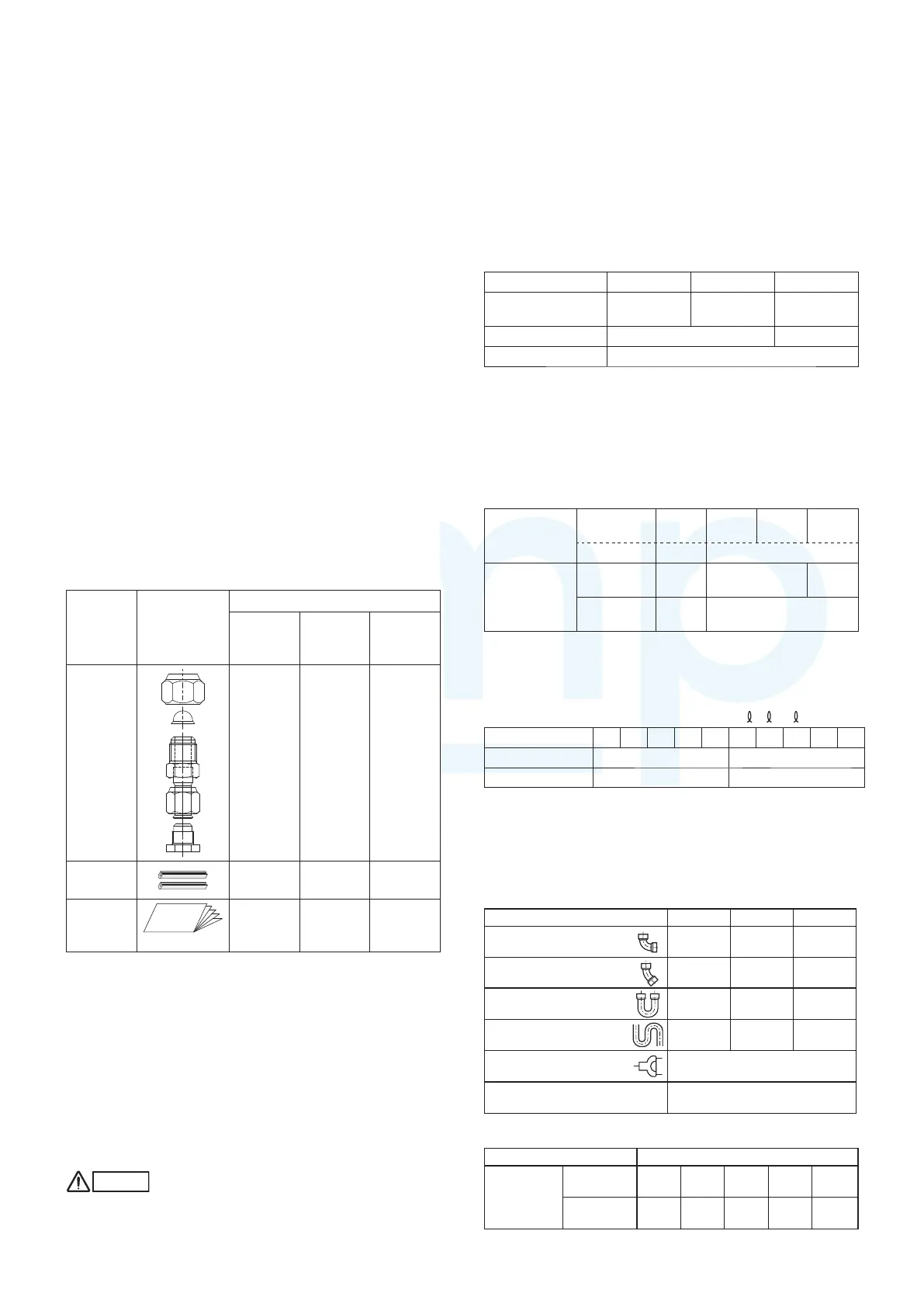
1-2. Accessories Supplied with Outdoor Unit
Table 1-1 (Outdoor Unit)
Part
name
Figure
Q’ty
U-4LE1E5
U-4LE1E8
(4 hp)
U-5LE1E5
U-5LE1E8
(5 hp)
U-6LE1E5
U-6LE1E8
(6 hp)
Tube
Discharge
Assy
001
Plastic bar
(L=115 mm)
222
Instruction
manual
paper
111
hp = horsepower
1-3. Type of Copper Tube and Insulation Material
If you wish to purchase these materials separately from a local
source, you will need:
1. Deoxidized annealed copper tube for refrigerant tubing.
2. Foamed polyethylene insulation for copper tubes as
required to precise length of tubing. Wall thickness of the
insulation should be not less than 8 mm.
3. Use insulated copper wire for field wiring. Wire size varies
with the total length of wiring. Refer to 4. ELECTRICAL
WIRING for details.
CAUTION
Check local electrical codes and regulations before
obtaining wire. Also, check any specified instructions or
limitations.
1-4. Additional Materials Required for Installation
1. Refrigeration (armored) tape
2. Insulated staples or clamps for connecting wire (See your
local codes.)
3. Putty
4. Refrigeration tubing lubricant
5. Clamps or saddles to secure refrigerant tubing
6. Scale for weighing
1-5. Tubing Size
Table 1-2 Main Tubing Size (LA)
4 hp 5 hp 6 hp
System
horsepower
456
Gas tubing (mm) ø15.88 ø19.05
Liquid tubing (mm) ø9.52
Unit: mm, hp = horsepower
Note : If the system consists of only one indoor unit with an
outdoor 6HP, the main tube of the unit (LA) should be
ø19.05. Convert ø19.05 to ø15.88 using a reducer
(field supply) close to the indoor unit and then make the
connection.
Table 1-3 Main Tubing Size After Distribution (LB, LC...)
Total
capacity after
distribution
Below kW
7.1
(2.5 hp)
12.1
(4 hp)
14.0
(5 hp)
15.5
(6 hp)
Over kW – 7.1(2.5 hp)
Tubing size
Gas tubing
(mm)
ø12.7 ø15.88 ø19.05
Liquid
tubing (mm)
ø9.52 ø9.52
Unit: mm, hp = horsepower
Note : In case the total capacity of connected indoor units
exceeds the total capacity of the outdoor units, select the
main tubing size for the total capacity of the outdoor units.
Table 1-4 Indoor Unit Tubing Connection (
1, 2... n–1)
Indoor unite type
22 28 36 45 56 73 90 106 140 160
Gas tubing (mm) ø12.7 ø15.88
Liquid tubing (mm)
ø6.35 ø9.52
Unit: mm
1-6. Straight Equivalent Length of Joints
Design the tubing system by referring to the following table for
the straight equivalent length of joints.
Table 1-5 Straight Equivalent Length of Joints
Gas tubing size (mm) 12.7 15.88 19.05
90° elbow
0.30 0.35 0.42
45° elbow
0.23 0.26 0.32
U-shape tube bend
(R60 − 100 mm)
0.90 1.05 1.26
Trap bend
2.30 2.80 3.20
Y-branch distribution
joint
Equivalent length conversion
not needed.
Ball value for service
Equivalent length conversion
not needed.
Table 1-6 Required Copper Tubing Dimensions Unit: mm
Material O
Copper
tubing
Outer
diameter
6.35 9.52 12.7 15.88 19.05
Wall
thickness
0.8 0.8 0.8 1.0 1.2
MiniVRFeng.indd7MiniVRFeng.indd7 2011/08/2613:45:112011/08/2613:45:11
www.ampair.co.uk | sales@ampair.co.uk
 Loading...