17
(8) To prevent malfunction of the air conditioner caused by electrical noise, care must be taken when wiring as follows:
●
The remote control wiring and the inter-unit control wiring should be wired apart from the inter-unit power wiring.
●
Use shielded wires for inter-unit control wiring between units and ground the shield on both sides.
(9) If the power supply cord of this appliance is damaged, it must be replaced by a repair shop appointed by the manufacturer,
because special purpose tools are required.
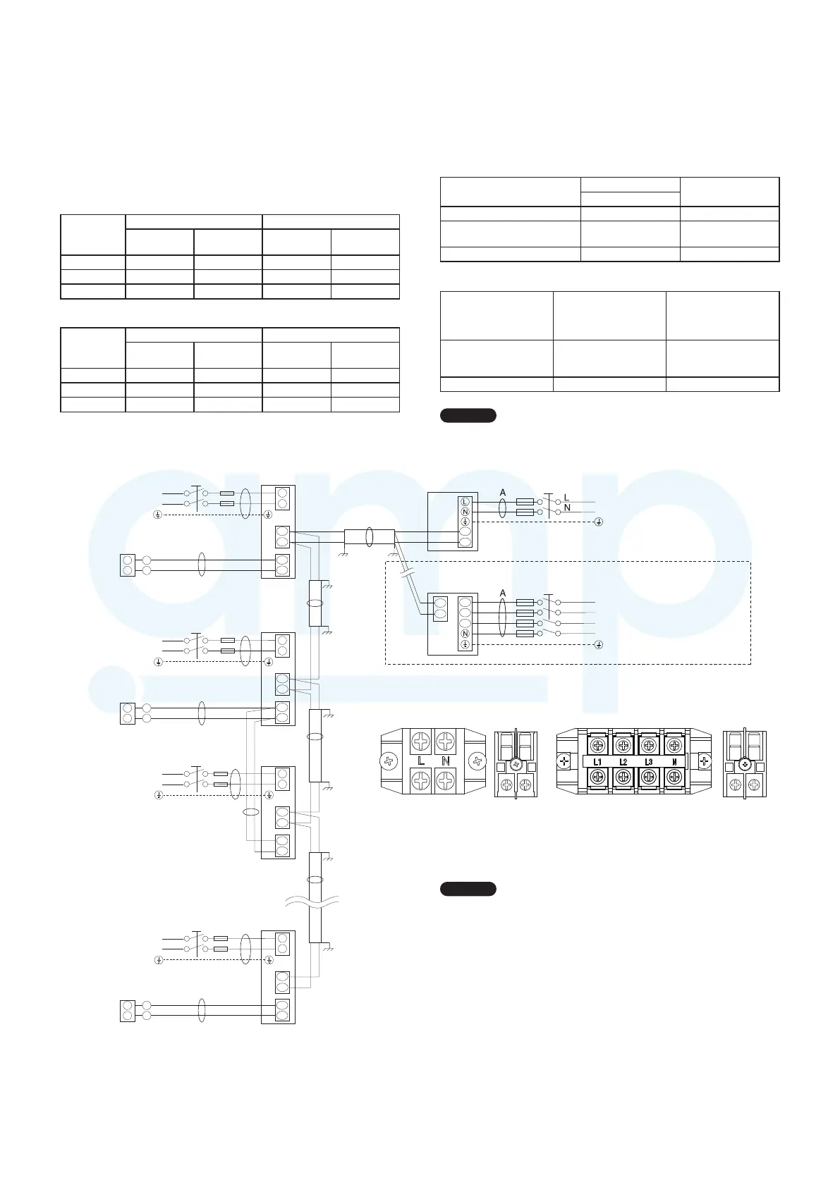
4-2. Recommended Wire Length and Wire Diameter
for Power Supply System
Outdoor unit (Single-phase)
(A) Power supply Time delay capacity
Wire size Max. length Fuse
Circuit
breaker
U-4LE1E5 4 mm
2
21 m 25 A 30 A
U-5LE1E5 6 mm
2
24 m 35 A 40 A
U-6LE1E5 6 mm
2
20 m 35 A 40 A
Outdoor unit (3-phase)
(A) Power supply Time delay capacity
Wire size Max. length Fuse
Circuit
breaker
U-4LE1E8 2.5 mm
2
58 m 20 A 20 A
U-5LE1E8 2.5 mm
2
49 m 20 A 20 A
U-6LE1E8 2.5 mm
2
41 m 20 A 20 A
4-3. Wiring System Diagrams
Indoor unit
Type
(B) Power supply
Time delay fuse or
circuit capacity
2.5 mm
2
K1 Max. 150 m 10 – 16 A
D1, L1, U1, Y1, T1, F1, M1,
P1, R1
Max. 130 m 10 – 16 A
E1 (73, 106, 140) Max. 60 m 10 – 16 A
Control wiring
(C) Inter-unit
(between outdoor
and indoor units)
control wiring
(D) Remote control
wiring
(E) Control wiring for
group control
0.75 mm
2
(AWG #18)
Use shielded
wiring*
1
0.75 mm
2
(AWG #18) 0.75 mm
2
(AWG #18)
Max. 1,000 m Max. 500 m Max. 200 m (Total)
NOTE
*
1 With ring-type wire terminal.
NOTE
(1) Refer to Section 4-2. “Recommended Wire Length
and Wire Diameter for Power Supply System” for the
explanation of “A”, “B”, “C”, “D” and “E” in the above
diagrams.
(2) The basic connection diagram of the indoor unit shows
the 7P terminal board, so the terminal boards in your
equipment may differ from the diagram.
(3) Refrigerant Circuit (R.C.) address should be set before
turning the power on.
(4) Regarding the R.C. address setting, refer to Section 7-4.
“Auto Address Setting”. Address setting can be executed
by remote controller automatically.
U2
U1
R2
R1
L
N
R2
R1
R2
R1
R2
R1
2
1
2
1
U2
U1
L
N
U2
U1
L
N
U2
U1
L
N
2
1
2
1
2
1
D
E
C
B
L
N
L
N
L
N
L
N
2
1
B
B
B
C
D
D
C
C
220 – 240V ~50/60Hz
WHT
BLK
WHT
BLK
WHT
BLK
220 – 240V ~50/60Hz
220 – 240V ~50/60Hz
220 – 240V ~50/60Hz
(No. 1)
(No. 2)
(No. n)
(No. 3)
U1
U2
1
2
L2
L1
L3
L1
L2
L3
N
LN
U1 U2
L2L1 L3 N
U1 U2
U1 U2 U1 U2
Power supply
Power supply
Power supply
Ground
Ground
Ground
Group control:
Remote
controller
Remote
controller
Remote
controller
Power supply
Ground
Indoor unit
Indoor unit
Indoor unit
Indoor unit
Ground
Ground
Ground
Ground
Ground
Ground
Outdoor unit : single-phase model
Power supply
220 – 240 V, single-phase, ~ 50 Hz
Ground
2P terminal board
Power supply Inter-unit
control wiring
Mini VRF System
Ground
In case of 3-phase power supply
Outdoor unit : 3-phase model
Power supply
380 – 415 V, 3-phase, ~ 50 Hz
Ground
Outdoor unit : single-phase model
4P terminal board
Power supply Inter-unit
control wiring
Outdoor unit : 3-phase model
MiniVRFeng.indd17MiniVRFeng.indd17 2011/08/2613:45:182011/08/2613:45:18
www.ampair.co.uk | sales@ampair.co.uk
 Loading...