13
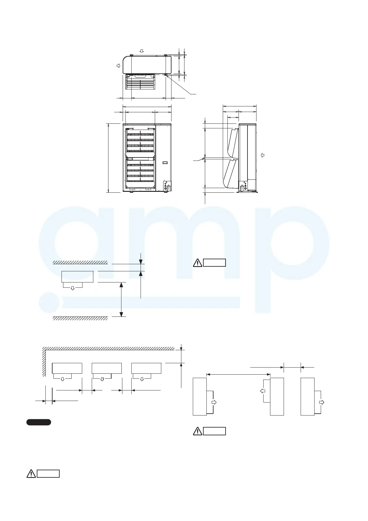
(1) Single-unit installation
Unit: mm
(2) Multiple-unit installation
Installation in lateral rows
Unit: mm
NOTE
●
The amount of space is required for removing the screws
on the rear of the unit. If in case the suffi cient space for
maintenance is ensured on the rear of the outdoor unit,
installation is possible with the space of both sides of not less
than 150mm where marked with * mark.
CAUTION
2-5. Dimensions of Air-Discharge Chamber
Reference diagram for air-discharge chamber (field supply)
Unit: mm
1330
940
56
(316)568
660
(110)
170
340
2020
380 1020
32
89
(88)
555 566
643
217
(303) 340
Required space around outdoor unit
If the air discharge chamber is used, the space shown below must be secured around the outdoor unit.
If the unit is used without the required space, a protective device may activate, preventing the unit from operating.
Air Intake
Air Intake
Installation anchoring holes (4-R6.5) / Anchor bolt M10
Air Intake
Air
discharge
Air
discharge
The top and both sides must remain open.
If there are obstacles to the front and rear of
the outdoor unit, the obstacle at either the
front or rear must be no taller than the height
of the outdoor unit.
Installation in front-rear rows
Installation with intakes facing
intakes or outlets facing outlets
Unit: mm
The front and both sides must remain open.
CAUTION
The front and top must remain open.
The obstacles must be no taller than the height
of the outdoor unit.
Min. 300 or more
Min. 1000 or more
CAUTION
Not less than 150* or more
Min. 250
or more
Min. 200
or more
Min. 250
or more
Min. 500
or more
Min. 150
or more
MiniVRFeng.indd13MiniVRFeng.indd13 2011/08/2613:45:152011/08/2613:45:15
www.ampair.co.uk | sales@ampair.co.uk
 Loading...