24
Lo Hi
R410A
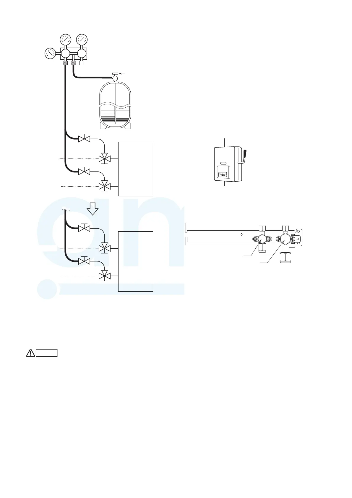
Fig. 6-5
Fig. 6-6
Finishing the job
(1) With a hex wrench, turn the liquid tube service valve stem
counterclockwise to fully open the valve.
(2) Turn the gas tube service valve stem counterclockwise to
fully open the valve.
CAUTION
To avoid gas from leaking when removing the charge hose,
make sure the stem of the gas tube is turned all the way
out.
(3) Loosen the charge hose connected to the gas tube service
port (for ø 7.94 mm tube) slightly to release the pressure,
then remove the hose.
(4) Replace the service port cap on the gas tube service port
and fasten the cap securely with an adjustable wrench or
box wrench. This process is very important to prevent gas
from leaking from the system.
(5) Replace the valve caps at both gas tube and liquid tube
service valves and fasten them securely.
This completes air purging with a vacuum pump. The air
conditioner is now ready for a test run. Refer to Section
“7. TEST RUN”.
Manifold valve
Pressure
gauge
Gas tube
Liquid tube
Open
Close
Close
Close
Outdoor unit
Valve
Liquid
Gas tube
Liquid tube
Close
Open
Open
Open
Outdoor unit
7. TEST RUN
7-1. Preparing for Test Run
● Before attempting to start the air conditioner, check the
following points.
(1) All loose matter is removed from the cabinet especially
steel filings, bits of wire, and clips.
(2) The control wiring is correctly connected and all electrical
connections are tight.
(3) The transportation pads for the indoor fan have been
removed. If not, remove them now.
(4) The power has been supplied to the unit for at least 5
hours before starting the compressor. The bottom of
the compressor should be warm to the touch and the
crankcase heater around the feet of the compressor should
be hot to the touch. (Fig. 7-1)
Fig. 7-1
(5) Both the gas and liquid tube service valves are open.
If not, open them now. (Fig. 7-2)
Fig. 7-2
(6) Request that the customer be present for the test run.
Explain the contents of the instruction manual, and then
have the customer actually operate the system.
(7) Be sure to give the instruction manual and warranty
certificate to the customer.
(8) When replacing the control PCB, be sure to make all the
same settings on the new PCB as were in use before
replacement.
The existing EEPROM is not changed, and is connected to
the new control PCB.
ON
(Power must be turned ON at least
5 hours before attempting test run)
Power mains switch
Liquid tube service cap
Gas tube service cap
MiniVRFeng.indd24MiniVRFeng.indd24 2011/08/2613:45:222011/08/2613:45:22
www.ampair.co.uk | sales@ampair.co.uk
 Loading...