28
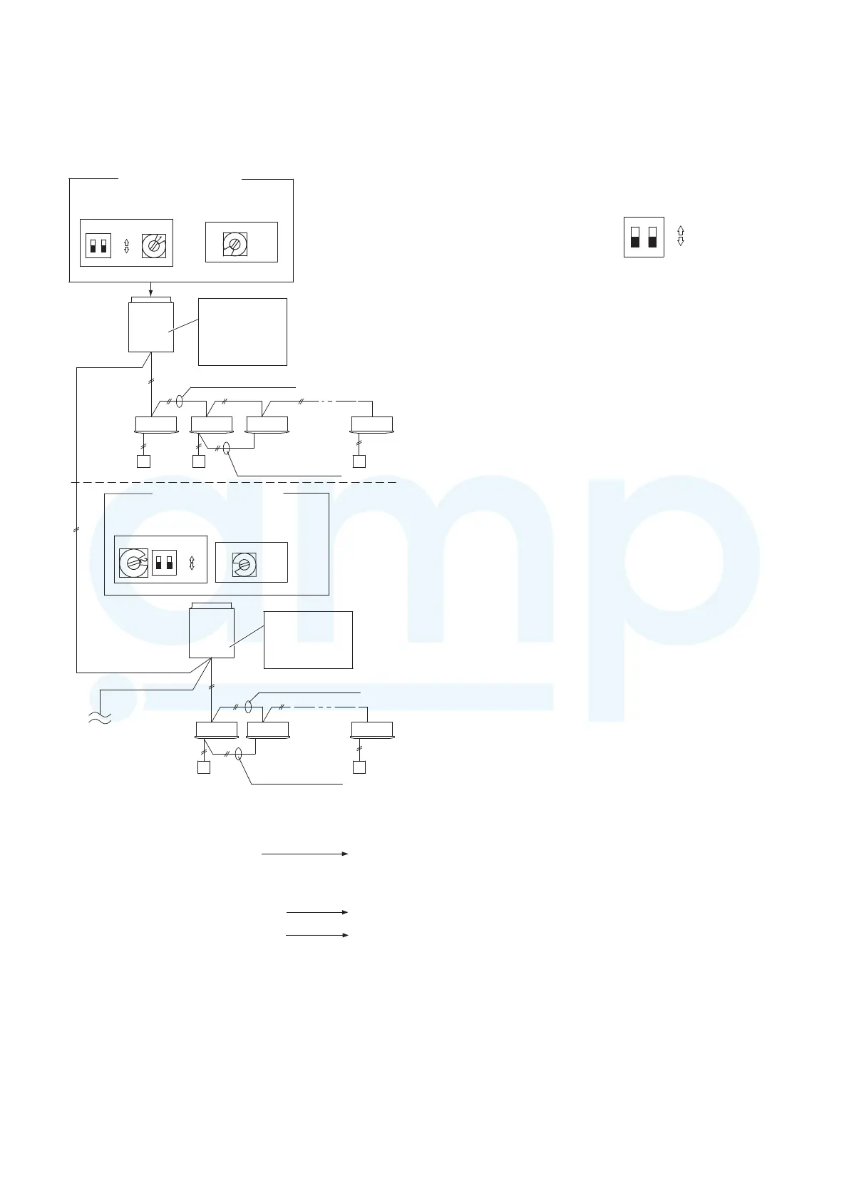
Basic wiring diagram: Example (2)
• If link wiring is used
*
When multiple outdoor units exist, remove the socket that is
used to short-circuit the terminal plug (CN-TERMINAL) from
all outdoor unit PCBs except for 1. Alternatively, move the
sockets to the “OPEN” side.
1-1 1-2
2-1 2-2 2-7
1-3 1-6
ON
1
2
(S004)
ON
1
2
(S003)
(S002)
(S004)
(S003)(S002)
ON
OFF
ON
OFF
6
7
Make settings as appropriate for the cases listed below.
Indoor and outdoor unit power can be
turned ON for each system separately.
<Case 2>
Indoor and outdoor unit power cannot
be turned ON for each system separately.
Automatic address setting in Heating mode
<Case 3A>
Automatic address setting in Cooling mode
<Case 3B>
No. 1 unit settings
System address
(system 1 setting)
No. of indoor units
(6 units setting)
Outdoor unit
system 1
Leave the socket
that is used to
short-circuit the
terminal plug.
(CN-TERMINAL)
Unit
No. 1
Inter-unit control wiring
Indoor unit
Remote
controller
Remote controller
communication wiring
No. 2 unit settings
System address
(system 2 setting)
No. of indoor units
(7 units setting)
Unit
No. 1
Outdoor unit
system 2
Leave the socket
that is used to
open circuit the
terminal plug
(CN-TERMINAL).
Indoor unit
Inter-unit control wiring
To other system
link wiring
Remote
controller
Remote controller
communication wiring
Fig. 7-7
<Case 2>
Automatic Address Setting (no compressor
operation)
● Indoor and outdoor unit power can be turned ON for each
system separately.
Indoor unit addresses can be set without operating the
compressors.
Automatic Address Setting from Outdoor Unit
1
On the outdoor unit control PCB, check that the system
address rotary switch (S002) is set to “1” and that the DIP
switch (S003) is set to “0”.
1
2
(These are the settings at the time of factory shipment.)
2
To set the number of indoor units that are connected to the
outdoor unit to 6 on the outdoor unit control PCB, set the
No. of indoor units rotary switch (S004) to “6”.
3
At the outdoor unit where all indoor and outdoor unit power
has been turned ON, short-circuit the automatic address
pin (CN-A.ADD) for 1 second or longer, then pull it out.
↓
(Communication for automatic address setting begins.)
↓
*
To cancel, again short-circuit the automatic
address pin (CN-A.ADD) for 1 second or
longer, then pull it out.
The LED that indicates automatic address
setting is in progress turns OFF and the
process is stopped.
(Automatic address setting is completed when LEDs 1 and
2 on the outdoor unit control PCB turn OFF.)
↓
4
Next turn the power ON only for the indoor and outdoor
units of the next (different) system. Repeat steps 1 – 3 in
the same way to complete automatic address settings for
all systems.
↓
5
Operation from the remote controllers is now possible.
*
To perform automatic address setting from the remote
controller, perform steps 1 and 2, then use the remote
controller complete automatic address setting.
Refer to “Automatic Address Setting from the Remote
Controller.”
ON
ON
OFF
MiniVRFeng.indd28MiniVRFeng.indd28 2011/08/2613:45:242011/08/2613:45:24
www.ampair.co.uk | sales@ampair.co.uk
 Loading...