7.4.3 I/O Allocation
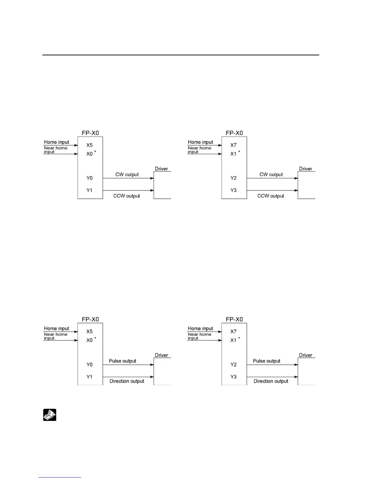
Double pulse input driver
(CW pulse input and CCW pulse input method)
- Two output contacts are used as a pulse output for “CW, CCW”.
- The I/O allocation of pulse output terminal and home input is determined by the channel used.
- Near home input is substituted by allocating the desired contact and turning on and off the <bit4> of
special data register DT90052.
- Set the control code for F171 (SPDH) instruction to “CW/CCW”.
* X0 or any other input can be specified for the
* X1 or any other input can be specified for the
Single pulse input driver
(pulse input and directional switching input method)
- One output point is used as a pulse output and the other output is used as a direction output.
- The I/O allocation of pulse output terminal, direction output terminal, and home input is determined by
the channel used.
- Near home input is substituted by allocating the desired contact and turning on and off the <bit4> of
special data register DT90052.
- Up to four driver systems can be connected.
- Specify "PLS+SIGN" for the control code of F171 to F177 instructions.
* X0 or any other input can be specified for the
near home input.
* X1 or any other input can be specified for the
near home input.
Reference: <7.2.1 Table of Specifications>
Phone: 800.894.0412 - Fax: 888.723.4773 - Web: www.clrwtr.com - Email: info@clrwtr.com
 Loading...


