Confirming the Unit Settings and Design ContentsFP2 Serial Data Unit
3 − 11
3.3 Confirming the I/O Contacts and Slot Number
3.3.3 Confirming the I/O Allocation and Slot Number
The I/O numbers and slot numbers are always necessary when creating a program.
These vary depending on the position at which the serial data unit is installed in the
backplane. Always check to see if the numbers match the design.
3.3.3.1 Confirming the I/O Number Allocations
The occupied I/O areas for all of the units mounted between the CPU unit and the FP2
serial data unit should be confirmed. These are allocated as I/O areas for the serial data
unit, starting from the serial number.
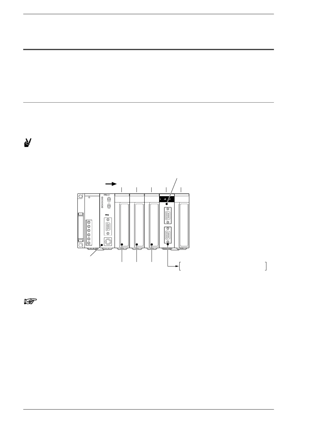
Example:
The following is an example of FP2 serial data unit being
mounted in succession following three 16−point I/O units.
SDU
SD RD ERR SD RD ERR AL
COM.1 COM.2
COM.1(RS232C)
COM.2(RS232C)
FP2 CPU unit
FP2 serial data unit
X0
XF
(WX0)
Y10
Y1F
(WY1)
Y20
Y2F
(WY2)
X30 to X2F (WX3) Y40 to Y4F (WY4)
01234
Slot No.
to to to
16−point output unit
16−point output unit
16−point output unit
16−point input unit
Notes
• If there are any empty slots between the CPU unit and the
serial data unit, check to see whether an I/O area has been
allocated to the empty slot.
• If I/O mount allocation and automatic allocation are being
carried out, 16 points for each type of allocation will
automatically be assigned to empty slots.
• If the CPU unit being used is a 2−module type, also check any
I/O areas occupying the units incorporated in the CPU unit.
• For information on how I/O allocations are made, refer to the
FP2/FP2SH User’s Manual.