KX-TCD400RUВ / KX-TCD400RUC / KX-TCD400RUF / KX-A140RUB / KX-A140RUC / KX-A140RUF
Items Adjustment
Point
Procedure* Check or
Replace Parts
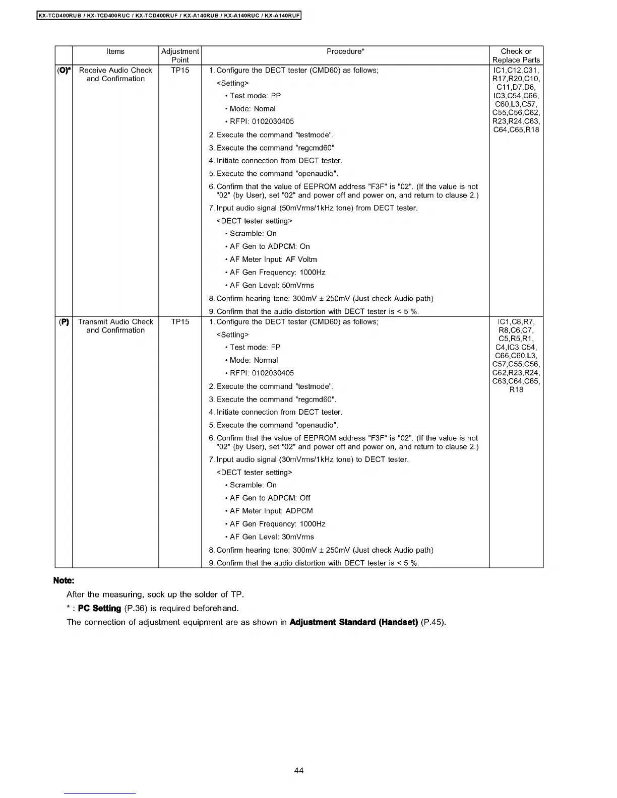
(O)*
Receive Audio Check
and Confirmation
TP15 1. Configure the DECT tester (CMD60) as follows;
<Setting>
• Test mode: PP
• Mode: Nomal
• RFPI: 0102030405
2. Execute the command "testmode".
3. Execute the command "regcmd60"
4. Initiate connection from DECT tester.
5. Execute the command "openaudio".
6. Confirm that the value of EEPROM address "F3F" is "02". (If the value is not
"02" (by User), set "02" and power off and power on, and return to clause 2.)
7. Input audio signal (50mVrms/1kHz tone) from DECT tester.
<DECT tester setting>
• Scramble: On
• AF Gen to ADPCM: On
• AF Meter Input: AF Voltm
• AF Gen Frequency: 1000Hz
• AF Gen -evel: 50mVrms
8. Confirm hearing tone: 300mV ± 250mV (Just check Audio path)
9. Confirm that the audio distortion with DECT tester is < 5 %.
IC1,C12,C31,
R17,R20,C10,
C11,D7,D6,
IC3,C54,C66,
060,-3,057,
C55,C56,C62,
R23,R24,C63,
C64,C65,R18
(P)
Transmit Audio Check
and Confirmation
TP15 1. Configure the DECT tester (CMD60) as follows;
<Setting>
• Test mode: FP
• Mode: Normal
• RFPI: 0102030405
2. Execute the command "testmode".
3. Execute the command "regcmd60".
4. Initiate connection from DECT tester.
5. Execute the command "openaudio".
6. Confirm that the value of EEPROM address "F3F" is "02". (If the value is not
"02" (by User), set "02" and power off and power on, and return to clause 2.)
7. Input audio signal (30mVrms/1kHz tone) to DECT tester.
<DECT tester setting>
• Scramble: On
• AF Gen to ADPCM: Off
• AF Meter Input: ADPCM
• AF Gen Frequency: 1000Hz
• AF Gen -evel: 30mVrms
8. Confirm hearing tone: 300mV ± 250mV (Just check Audio path)
9. Confirm that the audio distortion with DECT tester is < 5 %.
IC1,C8,R7,
R8,C6,C7,
C5,R5,R1,
C4,IC3,C54,
066,060,-3,
C57,C55,C56,
C62,R23,R24,
C63,C64,C65,
R18
Note:
After the measuring, sock up the solder of TP.
* : PC Setting (P.36) is required beforehand.
The connection of adjustment equipment are as shown in Adjustment Standard (Handset) (P.45).
44
 Loading...