Signal Name Function
M/nS Master/slave identification signal when SIC card (Future Option) as intersystem connection card is mounted. EMPR
inputs this signal and detects which the EMPR will be. H: Master L: Slave
MD0-2 Mode Control Terminal: Clock operation mode of CPU is set.MD2: L, MD1: L, MD0: H Fixed
MELODYSEL Melody IC Tune Name Select L: Ju te veux H: Minuet
MEC_MODE[3:0] Information Bit to know the memory mounting capacity etc. of EMEC card.Reserve at present.
MOHSEL Switching Signal between internal hold sound source and external hold sound H: Internal L: External
Mu/nA Switching Signal of Sound Compression Law H: Mu-Law, L: A-Law
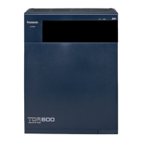
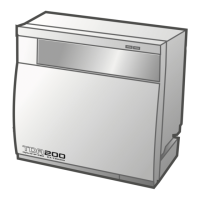
nTDA600 TDA600, TDA620 Identification Signal set on the back board. The EMPR inputs this signal and detects which the
EMPR will be. H: TDA200, L: TDA600
POWTYPE[0] -[1] Power Supply Type:
POWTYPE [1] [0]
M Power Supply attached L H
L Power Supply attached H L
nPRS_MEC Press MEC: Information of EMEC Card Attachment L: Attached, H: Not attached
nPRS_RMT Press RMT: Information of RMT Card Attachment L: Attached, H: Not attached
nPRS_SDB Press SD card: Information of SD Card Attachment L: Attached, H: Not attached
nRD Read: USB I/F, SD card I/F, ASIC, SRAM, Read signal for flash memory
RD/nWR Read/nWrite: Read/Write signal for SDRAM, BUS-M card.
nRESOUT Reset Out: Reset from CPU (IC200) to each card
nRESET Reset: Power-on reset signal
nRESETM Manual Reset (Software reset): Manual reset request signal for CPU
RINGER Ringer Signal: Outputs square-wave of 16Hz/20Hz/25Hz as source signal of ringer
RING_SYNC Trigger Signal of Ringer Signal generation timing to each internal line card
nRTS2 Request To Send to RS-232C connector
RTS_RMT Request to Send: Flow signal for modem
RXD2 Receive Data from RS-232C connector
RXD_RMT Serial Data Output Terminal: ASIC
SDCD SD Card Detect Input
SDCLK SD Card Clock Out
SDCMD SD Command
SDDAT0-3 SD Card Data
SDWP SD Card Write Protect Input
SHW_CLK Intersystem Highway Clock Signal (4MHz) Bit clock of intersystem highway.
SHW_FH Intersystem Highway Synchronous Signal (8KHz) 8KHz frame synchronous signal of intersystem highway
TXD2 Transmit Data to RS-232C connector
TXD_RMT Serial Data Input Terminal: Data receiving terminal from RMT to UART in the ASIC
nUB Upper Byte Select: SRAM
USB_D+ USB Data +
USB_D- USB Data -
VBUS Bit indicating that power source is supplied to USB bus [Host (PC etc.) is connected.] H: Host connected L: Host not
connected
VREF Reference Voltage for MOH Circuit Intermediate potential of +15V
nWAIT Wait: Hardware wait request signal for bus timing between CPU and ASIC
nWE Write Enable: WE signal of SRAM
34
KX-TDA600BX
 Loading...