2) DC loop formation circuit
In the off hook status, PC5 is ON.
DC loop path:
Tip→L1→D1→D2→D3→Q10(E-C)→Q1(C-E)→R9→R8→D3→L1→Ring
At this time, the output of the photo coupler PC1 changes level from High to low.
Ring→L1→D3→Q10(E-C)→Q1(C-E)→R9→R8→D3→D2→D1→L1→Tip
At this time, the output of the photo coupler PC2 changes level from High to low.
Afterwards, CPU monitor this change (low level to high level). If the high level continues for a specified time set by system data
programming. CPU assumes that CO line has become On hook status. And the CO line circuits is restored to the idle status.
3) Pulse dial transmission circuit
When the Off hook status, pulse dial transmission is executed by alternating On hook and Off hook. The status of On hook or
Off hook is controlled by the switching transistor Q10.
22
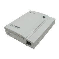
KX-TEA308CE
 Loading...