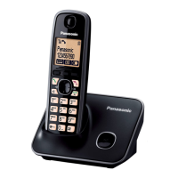
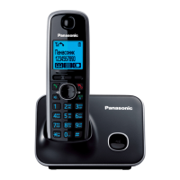
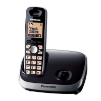
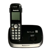
This document serves as a service manual for Panasonic Digital Cordless Phones, specifically models KX-TG6611CXB, KX-TG6611CXS, KX-TG6612CXB, KX-TG6612CXS, KX-TGA661CXB, and KX-TGA661CXS. These models are Caller ID compatible. The 'B' suffix denotes a Black Version, and 'S' denotes a Silver Version. The CXB/CXS models are designed for Singapore, Indonesia, and Vietnam markets. The KX-TGA661 is an optional accessory that includes a handset and a charger.
Function Description:
The Panasonic Digital Cordless Phones operate on the DECT (Digital Enhanced Cordless Telecommunications) standard, supporting GAP (Generic Access Profile). The system consists of a base unit, handset(s), and optionally a charger unit.
The Base Unit handles the core telecommunication functions, including:
- Telephone Line Interface: Detects bell and clip signals, and manages the on/off hook circuit. In standby mode, the unit is on-hook to reduce DC loop current. When a ring signal is detected or a handset goes off-hook, the circuit provides an off-hook condition, allowing DC current flow and signal transmission.
- Transmitter/Receiver: Processes audio and DTMF tone signals. It transmits and receives voice and data signals through the antenna on a carrier frequency. The voice signal from the TEL LINE interface is amplified, converted to a digital audio stream, encrypted, scrambled, and formatted into a DECT frame. The carrier frequency is modulated, and the RF signal is amplified and radiated. Conversely, incoming RF signals are downconverted, demodulated, decoded, and converted back to analog audio for the TEL LINE interface.
- Power Supply Circuit: Provides power to the DECT BBIC, QSPI FLASH MEMORY, EEPROM, and Charge Contact from the AC Adaptor.
- Pulse Dialing: Generates dial pulses using the hookswitch (Q3, Q4) controlled by the HOOK signal. The PULSE_DIAL signal forces line impedance low during pause intervals between pulses.
The Handset integrates several key functions:
- DECT BBIC (Base Band IC): Manages all data signals (ACK/CMD), interfaces (Key, Detector Circuit, Charge, DC/DC Converter, EEPROM, LCD, RF Power Amp.), PLL Oscillator, Detector, Compress/Expander, Reception, and an integrated 1.9GHz PA for DECT.
- QSPI FLASH MEMORY: Stores the main program download area.
- EEPROM: Stores temporary operating parameters for RF, etc.
- Power Supply Circuit/Reset Circuit: Manages power-on sequence and generates reset signals. It also detects "Battery Low" and "Power Down" conditions based on battery voltage.
- Charge Circuit: Detects when the handset is placed on the base unit for charging and controls the charge current.
- Speakerphone: Utilizes the hands-free loudspeaker for ring alarms and speakerphone functionality.
Important Technical Specifications:
- Standard: DECT (Digital Enhanced Cordless Telecommunications), GAP (Generic Access Profile).
- Number of Channels: 120 Duplex Channels.
- Frequency Range: 1.88 GHz to 1.90 GHz.
- Duplex Procedure: TDMA (Time Division Multiple Access).
- Channel Spacing: 1,728 kHz.
- Bit Rate: 1,152 kbit/s.
- Modulation: GFSK (Gaussian Frequency Shift Keying).
- RF Transmission Power: Approx. 10 mW (average power per channel).
- Voice Coding: ADPCM 32 kbit/s.
- Power Source (AC Adaptor): 100-240 V AC, 50/60 Hz.
- Base Unit: PNLV226BXOZ.
- Charger: PNLV226BXOZ.
- Power Consumption:
- Base Unit: Standby approx. 0.4 W, Maximum approx. 2.3 W.
- Charger: Standby approx. 0.1 W, Maximum approx. 1.8 W.
- Operating Conditions: 0 °C-40 °C, 20%-80% relative air humidity (dry).
- Dimensions:
- Base Unit: Approx. 126 mm x 90 mm x 77 mm.
- Handset: Approx. 49 mm x 29 mm x 159 mm.
- Charger: Approx. 73 mm x 76 mm x 43 mm.
- Mass (Weight):
- Base Unit: Approx. 140 g.
- Handset: Approx. 130 g.
- Charger: Approx. 50 g.
- Operation Range: Up to 300 m outdoors, Up to 50 m indoors.
- Analog Telephone Connection: Telephone Line.
- DECT Repeater: KX-A405.
Usage Features:
- Caller ID Compatible: Supports Caller ID functionality.
- Rechargeable Batteries: The unit can use other rechargeable batteries, though proper operation is not guaranteed. Battery strength indication may require recharging after disconnection/reconnection.
- Phonebook Copying: Allows copying of handset phonebook items to another compatible Panasonic handset, useful for data transfer during repairs or replacement.
- User Setting Reset: Provides an option to reset units to factory settings, erasing stored phone numbers and caller lists. This operation differs for resetting both base unit and handset, or only the handset.
- Power Failure Behavior: In case of AC power loss, the base unit can detect this and allow the handset battery to supply power to the base unit, enabling continued limited operation.
- Engineering Mode: Provides access to advanced settings for service technicians, including reading and writing EEPROM data, and adjusting various parameters.
Maintenance Features:
- Safety Precautions: Emphasizes the importance of using experienced repair technicians due to potential dangers from electricity. Special components critical for safety are marked and must be replaced with manufacturer-specified parts.
- Lead-Free Solder (PbF) Information: Details the use of lead-free solder in manufacturing and provides instructions for its use during service and repair, including higher melting points and precautions to prevent damage.
- Troubleshooting Guide: Includes flowcharts and symptom-based troubleshooting for the base unit, handset, and charger unit. It covers power issues, bell reception, battery charge, link problems, RF part, handset transmission/reception, DTMF dial, and Caller ID reception.
- Disassembly and Assembly Instructions: Provides step-by-step guides for disassembling and assembling the base unit, handset, and charger unit, including specific screw locations and methods for opening cabinet covers.
- LCD Replacement: Detailed instructions for replacing the handset LCD, including peeling off the FFC, fitting the heatseal, and heat welding. It also specifies tolerances for vertical and horizontal intervals.
- Measurements and Adjustments: Outlines required equipment (digital multi-meter, oscilloscope, frequency counter, DECT tester) and methods for connecting JIG cables for PC-based adjustments.
- IC/X'tal Replacement Procedures: Provides instructions for downloading programming data and adjustment data to FLASH, EEPROM, and X'tal after replacement, ensuring proper unit operation.
- RF Specification Checks: Details parameters for TX Power, Modulation, Frequency Offset, Frequency Drift, RX Sensitivity, Timing Accuracy, and Power RAMP for both base unit and handset, with references to check points for adjustment.
- Speaker/Receiver Check: Instructions for checking the resistance of the handset speaker or receiver using a digital voltmeter.
- Frequency Table: Provides a table of transmit and receive frequencies for each channel in MHz for both base unit and handset.
- Flat Package IC Replacement: Instructions for replacing flat package ICs, including temporary fixing, flux application, and soldering techniques.
- Shield Case Replacement: Instructions for removing and installing the shield case, including cutting along perforations and melting solder.
- Terminal Guide: Provides terminal guides for ICs, transistors, and diodes in both base unit and handset.
- Schematic Diagrams: Includes detailed schematic diagrams for the base unit, handset, and charger unit, with notes on DC voltage measurements and important safety notices for marked components.
- Printed Circuit Board Views: Provides component views for the base unit main board, handset main board, and charger unit board.
- Exploded View and Replacement Parts List: Lists all cabinet and electrical parts for the base unit, handset, and charger unit, including part numbers, descriptions, and remarks. It also includes information on Retention Time Limited (RTL) parts and special tools for certain replacements.