STEP
No.
Ref.
No.
PART REMOVE
Section
No.
NOTE
2
2,3
--
Side Case L Unit
Front Case Ass’y
A B C D E F
3
4
5
1
6
7
8
9
6 , (L-2), P1,
FP6, FP9
404 -1
2 , FP1
404 -3
510 -4
2 ,
404 -5 -5510
, 3(L-4)
404 -7
2
404 -6
E10
E20
11
1
, 3(L-3), B1,
FP2, FP3, FP4,
FP5, FP7, FP8,
FP10, FP301,
FP701
4
Main C.B.A.
-
6
Lens Ass’y
-
6(L-1)
1
Cassette Cover
Ass’y
MAIN PARTS PORTION
8
Mechanism
Chassis Ass’y
5
Rear C.B.A.
-
7
Top Case & EVF
Ass’y
-
-----
-----
-
Side Case R Ass’y
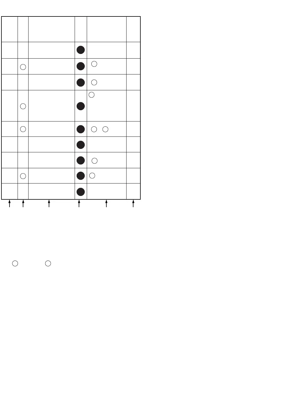
How to read chart shown above:
A: Order of Procedure steps.
When reassembling, perform steps(s) in reverse order.
B: Ref No.
C: Part to be removed or installed.
D: Section No.
E: Identification of part to be removed, unhooked, unlocked,
released, unplugged, unclamped, or unsoldered.
3
404 404
= 3 Screws , 2(L-1) = 2 Looking Tabs (L-1)
F: Refer to "Notes in chart."
1
1
1
1
1
1
1
1
1