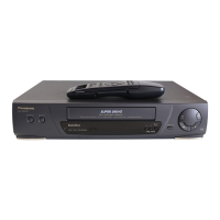
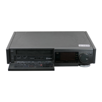
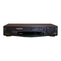
1. INTRODUCTION
This service manual contains technical information which will allow service personnel to understand and
service this model.
If the circuit is changed or modified, this information will be followed by supplementary service manual to be
filed with original service manual.
NOTE:
Adjustment procedures, Disassembly Procedures and Assembly Procedures for Mechanism Chassis are separated
volume from this Service Manual.
Please refer to the Service Manual for DJ-Mechanism Chassis. (Order No. VMD9706005A8)
1.1. CMPONENT REFERRENCE TABLE
If you have the reference number of each component and have no idea where it is, use the following table to
find out the C.B.A. and/or diagram.
Reference-Series- Located C.B.A. Name of Diagram Remarks
1000 Series VEP06D55A RF I/F SECTION IN MAIN
1100 Series
1200 Series
VEP06D55A POWER SECTION IN MAIN
1100 Series
1200 Series
VEP01868A SUB POWER<POWER SECTION IN MAIN>
1500 Series VEP06D55A RF I/F SECTION IN MAIN
1500 Series VEP000D5B MOTOR DRIVE<DIGITAL (SYSTEM CONTROL&
SERVO SECTION)>
2000 Series VEP03F39A DIGITAL (LSI MICON SECTION)
2500 Series VEP03F39A DIGITAL (SYSTEM CONTROL& SERVO SECTION)
3000 Series VEP03F39A DIGITAL (VIDEO 1 SECTION)
3100 Series VEP03F39A DIGITAL (VIDEO 1 SECTION)
3200 Series VEP03F39A DIGITAL (VIDEO 2 SECTION)
3600 Series VEP06D55A VIDEO SECTION IN MAIN
3700 Series VEP03F39A DIGITAL (DIGITAL I/F SECTION)
3900 Series VEP03F40A INPUT/OUTPUT
4000 Series VEP06D55A RF I/F SECTION IN MAIN
4200 Series VEP03F39A DIGITAL (VIDEO 1 SECTION)
4300 Series VEP06D55A AUDIO SECTION IN MAIN
4500 Series VEP03F39A DIGITAL (VIDEO 1 SECTION)
4700 Series VEP06D55A VIDEO SECTION IN MAIN
4800 Series VEP07A24A TIMER
4900 Series VEP06D55A RF I/F SECTION IN MAIN
4900 Series VEP03F40A INPUT/OUTPUT
4950 Series VEP06D55A RF I/F SECTION IN MAIN
5000 Series VEP05352A HEAD/ REC AMP
 Loading...
