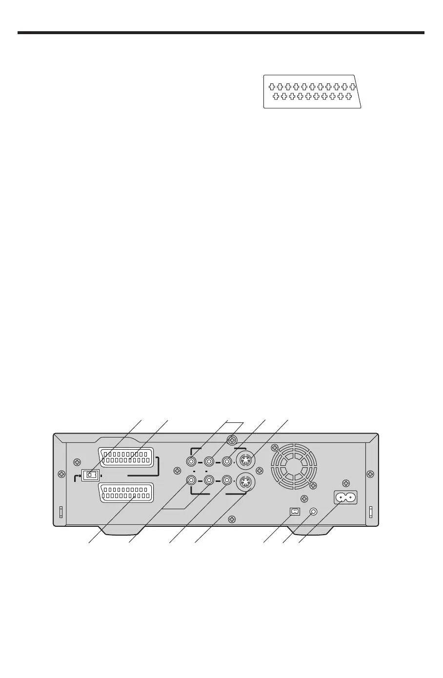
Rear
35 NORMAL/S-VIDEO OUT switch for AV1 only
36 AV1 21-pin Scart socket [AV1 (TV)]
37 Audio Monitor Output sockets [AUDIO OUT (AV3)]
38 Video Monitor Output socket [VIDEO OUT (AV3)]
39 S-Video Output socket (S-VIDEO OUT)
40 AV2 21-pin Scart socket [AV2 (EXT)]
The scart terminal is also called “Peritel”, “Euro
Connector” or “Euro AV”.
NORMAL (AV1/AV2) S-VIDEO (AV1)
1 AUDIO OUTPUT 1 AUDIO OUTPUT
CH2 (R) CH2 (R)
2 AUDIO INPUT 2 AUDIO INPUT
CH2 (R) CH2 (R)
3 AUDIO OUTPUT 3 AUDIO OUTPUT
CH1 (L) CH1 (L)
4 AUDIO GND 4 AUDIO GND
5 BLUE GND 5 No connection
6 AUDIO INPUT 6 AUDIO INPUT
CH1 (L) CH1 (L)
7 BLUE 7 No connection
8
SWITCHING VOLTAGE
8 SWITCHING VOLTAGE
9 GREEN GND 9 No connection
10 Connection 10 Connection
(Only when NV-DV2000 is off)
11 GREEN 11 No connection
12 No connection 12 No connection
13 RED GND 13 C OUT GND
14 BLANKING GND 14 No connection
15 RED 15 C OUT
16 BLANKING 16 No connection
17 VIDEO OUTPUT GND 17 Y OUT GND
18 VIDEO INPUT GND 18 VIDEO INPUT GND
19 VIDEO OUTPUT 19 Y OUT
20 VIDEO INPUT 20 VIDEO INPUT
21 GND 21 GND
Caution: RGB reservation for only E/E operation when
connecting the Pay TV decoder.
135791113151719
21
2468101214161820
Front (Explanation)
VCR-ON/OFF button (
]]
]]
]/I)
Press to switch the VCR from on to standby mode or
vice versa. In standby mode, the unit is still connected
to the mains.
Edit Terminal switch
By connecting a video movie camera or VCR with an
EDIT socket via an Edit cable, various kinds of editing
functions can be performed more quickly and
efficiently between two VCRs or between a VCR and
a video movie camera.
DV Input/Output socket [DV1/DV2(¥)]
To connect the DV cable to digital video equipment
with iEEE 1394-1995.
“¥” is the logo marked on products conforming with
the “i.LINK” specifications. For further details on the
DV terminal.
Edit Mode switch
PLAYER: When this VCR is used as the playback
VCR during editing operations.
RECORDER:When this VCR is used as the recording
VCR during editing operations.
≥ Normally set at this position.
PASSIVE: When operating this VCR using another
VCR or an editing controller.
AV1 21-pin Scart socket [AV1 (TV)]
This 21-pin scart terminal carries input and output
signals for both picture and sound. TV sets equipped
with a similar socket can be connected here.
AV1
(
TV
)
AV2
(
EXT
)
MONITOR OUT
R AUDIO L
VIDEO S-VIDEO
DIGITAL STILL
PICTURE OUT
AC INT
SECTEUR
T
¥
DV1
AV3 IN
S-VIDEO OUT
NORMAL
35
36
37
38
39
40
41
42
43
44
46
45
41 Audio Input sockets [AUDIO IN (AV3)]
42 Video Input socket [VIDEO IN (AV3)]
43 S-Video Input socket [S-VIDEO IN (AV3)]
44 DV Input/Output socket [DV1(¥)]
45 DIGITAL STILL PICTURE OUT socket
46 AC Input socket (AC IN)