29
8.4. Disassembly Procedures Mecha. Unit
Flow-Chart for Disassembly Procedure
Fig. M1
Fig. M2
No. Item / Part Fig. Removal (Screw, Connector, Flex. & Other)
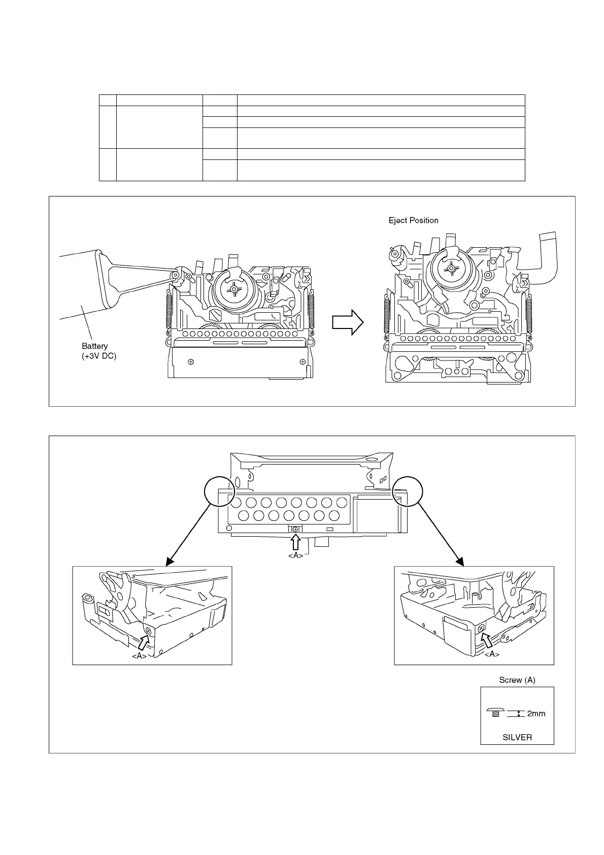
1 Cassette Up Unit Fig. M1 It makes the mechanism position in Eject condition (For Battery)
Fig. M2 3-Screws (A)
Fig. M3 3-Tabs
I remove the piece arrangement unit from rail department
2 Cylinder Unit Fig. M4 1-Screw (B)
Fig. M5 3-Screw (C)
Cylinder Unit