43
9.4. Mechanical Adjustment Procedures
9.4.1. Adjustment item
9.4.2. Adjustment procedures
lLinearlty adjustment & BER value confirmation
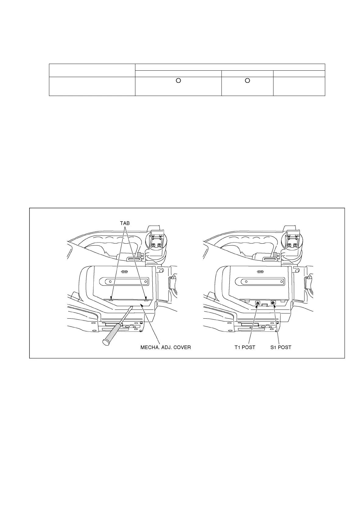
1. Remove the mechanism adjustment cover of tis machine as shown in Fig. D1.
2. The spcial tool at the time of electricity adjustment is connected.
Reference of the connection figure of electricity adjustment.
3. The enbelope detection spcial tool board (VFK1641) is connected to EVR adjustment board as shown in Fig. D2.
4. The enbelope detection spcial tool board is connected to oscilloscope as shown in Fig. D2.
5. The post is adjusted with the post driver(VFK1899) so that recycles the normal tape which recorded NTSC signal and the
detection wave-link become a flat as shown in Fig. D3.
*At the time of the clyinder unit exchange unnecessary.
6. The post is adjusted with the post driver so that recycles a alignment tape(VFM3110EDS) and the detection wave-link
become a flat once again.
7. Recycling the tape that video-taped it wirh this machine after adjustment, the BER value is confirmed withthe item of the BER
the item of the BER confirmation of expert soft inside.
Fig. D1
Item Adjustment at the time of the part exchange
Half finished goods mechanism Clyinder Remarks
Linearlty adjustment
&
BER value confirmation