15
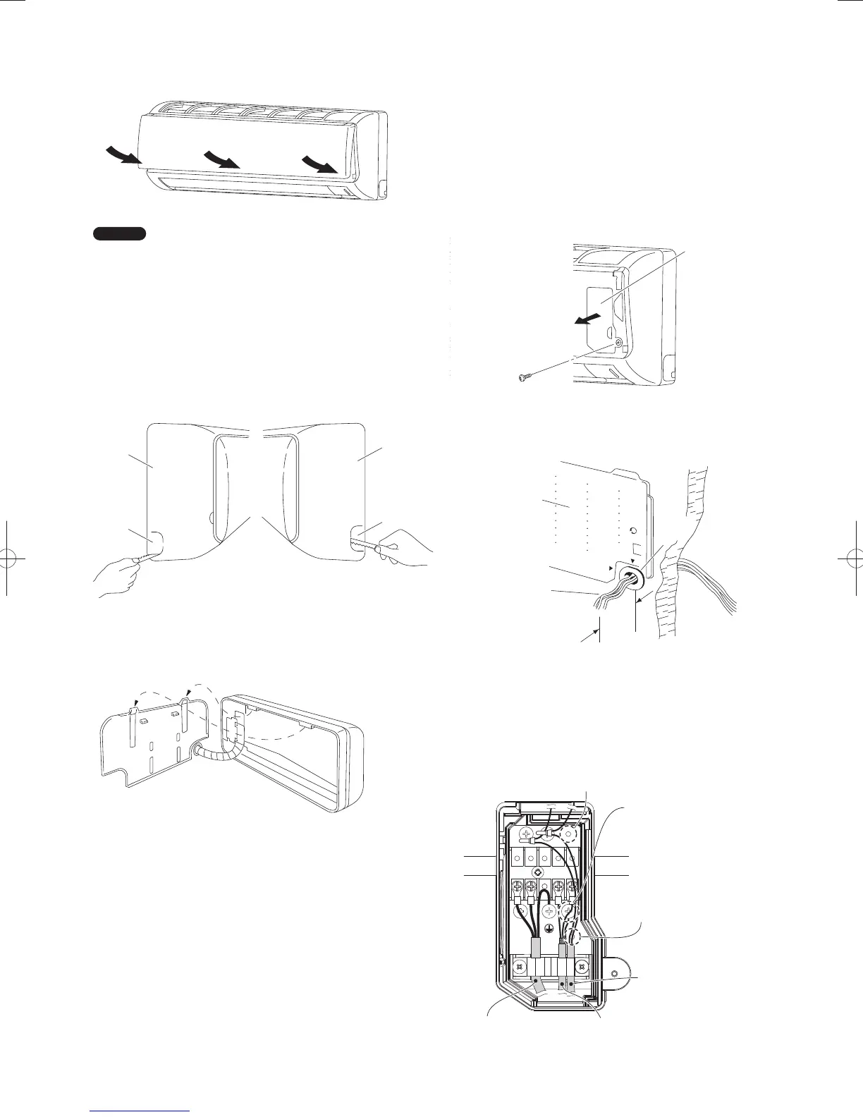
(b) Press the bottom right and left corners and center of
the air intake grille to attach it to the indoor unit.
(Fig. 3-45)
Fig. 3-45
NOTE
Attach so that the round pins at the top right and left corners of
the air intake grille are inserted into the grooves at the top right
and left of the indoor unit.
3-15. Shape the Indoor Side Tubing
(1) Arrangement of tubing by directions
a) Right or left tubing
Cut out the corner of the right/left frame with a
hacksaw or the like. (Figs. 3-46 and 3-47)
b) Right-rear or left-rear tubing
In this case, the corner of the frame need not be cut.
Fig. 3-46 Fig. 3-47
(2) To mount the indoor unit on the rear panel:
Hang the 2 mounting slots of the unit on the upper
tabs of the rear panel. (Fig. 3-48)
Fig. 3-48
3-16. Wiring Instructions
General precautions on wiring
(1) Before wiring, confirm the rated voltage of the unit as
shown on its nameplate, then carry out the wiring closely
following the wiring diagram.
(2) Provide a power outlet to be used exclusively for each
unit, with a power supply disconnect and circuit breaker for
overcurrent protection provided in the exclusive line.
(3) To prevent possible hazard due to insulation failure, the
unit must be grounded.
(4) Each wiring connection must be done tightly and in
accordance with the wiring system diagram. Wrong wiring
may cause the unit to misoperate or become damaged.
(5) Do not allow wiring to touch the refrigerant tubing,
compressor, or any moving parts of the fan.
(6) Unauthorized changes in the internal wiring can be very
dangerous. The manufacturer will accept no responsibility
for any damage or misoperation that occurs as a result of
such unauthorized changes.
3-17. Wiring Instructions for Inter-unit Connections
(1) Grasp both ends of the air intake grille, and remove it by
opening toward the front and pulling it toward you.
(2) Remove the screw on the right side cover plate and open
the cover. (Fig. 3-49)
Fig. 3-49
(3) Insert the inter-unit wiring into the through-the-wall PVC
pipe. Lead the power wiring into the room allowing approx.
25 cm to extend from the wall face. (Fig. 3-50)
25 cm
Fig. 3-50
(4) Route the inter-unit wiring from the back of the indoor unit
and pull it toward the front for connection. (Fig. 3-51)
(5) Connect the inter-unit wiring to the corresponding terminals
on the terminal plate (Fig. 3-51) while referring to the wiring
diagram.
Protective ground screw
(External Solenoid Valve Kit for 3WAY)
Use this screw when
connecting the shield
for the Inter-unit control
wiring to ground.
Functional ground screw
(External Electronic Expansion
Valve Kit and Schedule Timer)
Remote Control Wiring
Inter-unit Control Wiring
Power Supply
L1 L2 N U1 U2
Fig. 3-51
Frame
Left tubing
outlet
Frame
Right tubing
outlet
Cover
Rear
panel
Wiring
Plastic
cover
PanaIndoor-337012Eng.indb15PanaIndoor-337012Eng.indb15 2012/03/2116:20:472012/03/2116:20:47
 Loading...


