26
36
54 54
161
26
15
57
100
177
230
615
155
107
205
260
213
76
67
156
C
B
A
R25
Fig. 3-108
Unit: mm
Side panel
Refrigerant tubing space for
downward tubing
Air outlet
Air inlet
Rear-tube outlet
■ Floor Standing Type (P1 Type)
Concealed Floor Standing Type (R1 Type)
3-28. Required Minimum Space for Installation and
Service
Install the unit where cooled or heated air from the unit can
circulate well in the room. Do not put obstacles which may
obstruct the air flow in front of the air intake and outlet grilles.
Fig. 3-107
NOTE
Ensure there is adequate space for maintenance of the
electrical component box, air filter, and refrigerant tubes.
Horizontal view Vertical view
min.
10 cm
min.
10 cm
min. 100 cm
min. 100 cm
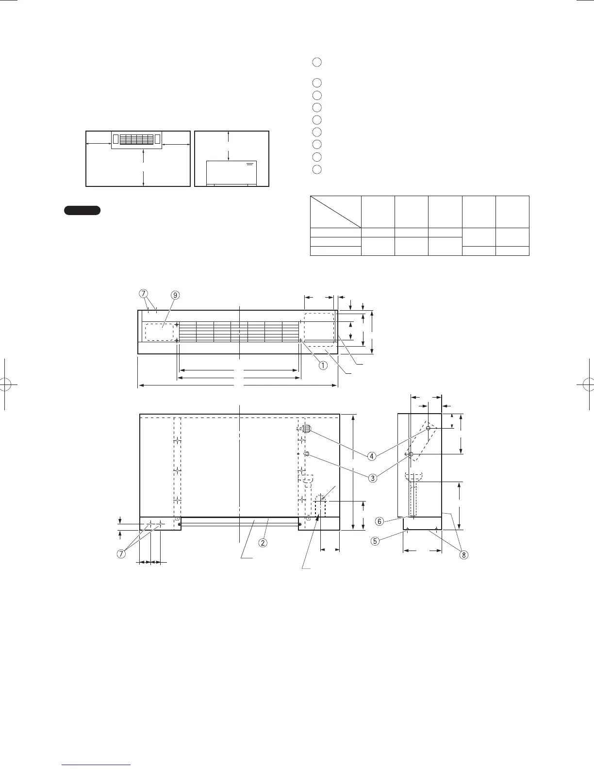
3-29. Dimensions and Part Names
Floor Standing Type (P1 Type)
4-ø12 holes (for fastening the indoor unit to the floor with
screws)
Air filter
Refrigerant connection outlet (liquid tube)
Refrigerant connection outlet (gas tube)
Level adjusting bolt
Drain outlet (20 A)
Power cord outlet (downward, rear)
Refrigerant tubing outlet (downward, rear)
Location for mounting the remote controller (remote
controller can be attached within the room)
Table 3-3
Unit: mm
Length
Type
ABC
Liquid
tube
Gas
tube
22, 28, 36 1065 665 632
ø6.35 ø12.7
45, 56
1380 980 947
73 ø9.52 ø15.88
PanaIndoor-337012Eng.indb26PanaIndoor-337012Eng.indb26 2012/03/2116:20:492012/03/2116:20:49
 Loading...


