39
(2) Install the ceiling panel onto the indoor unit. (See Fig. 7-15.
The connector is on the electrical component box.)
[1] Fasten the stationary fasteners (opposite side of the
connector) to the indoor unit. (Fig. 7-16a) Next, lift up
the connector side and fasten the movable fastener
onto the indoor unit. (Fig. 7-16b)
Fig. 7-16a Fig. 7-16b
At this time, check that the movable fastener locks
with a click sound onto the indoor unit.
The ceiling panel includes these provisional-fastening
fasteners to facilitate installation onto the indoor unit.
[2] Check that the ceiling panel is provisionally fastened to
the indoor unit.
[3] Next use the supplied screws (four M5 × L40 screws
with washers) to fasten the ceiling panel in place.
[4] When installation of the ceiling panel is completed,
connect the 8P red connector inside the indoor unit
electrical component box to the connector from the
ceiling panel. (Fig. 7-17) (If this connector is not
connected, the error message “P09” is displayed on
the remote controller and the unit will not operate.)
Connecting the connector
Fig. 7-17
Operating the movable fastener
Fig. 7-18
[5] Check that the ceiling panel and ceiling surface are
in tight contact, then install the air filter and air intake
panel.
7-5. Removing the Ceiling Panel for Servicing
When removing the ceiling panel for servicing, remove the air-
intake grille and air filter, disconnect the wiring connector inside
the electrical component box, and then remove the 4 mounting
screws.
Release one side of the panel by pressing the panel catch in
the direction of the arrow. (See Caution.) Completely remove
the ceiling panel by disengaging the stationary catch.
(Figs. 7-16a and 7-16b)
CAUTION
When the air filter is removed, the rotator and live parts are
exposed at the openings and these can cause a danger.
Therefore be particularly careful.
Connector (8P, red)
Panel connector
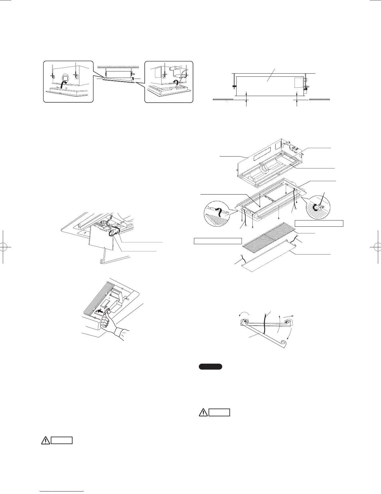
■ 2-Way Cassette Type (L1 Type) (For 73 Type)
7-6. Before Installing the Ceiling Panel
(1) Adjust the distance between the unit and the surface of the
ceiling (60 mm) using the 2 hexagonal nuts as shown in
Fig. 7-19 while following the installation gauge.
60
60
Fig. 7-19
(2) Remove the air-intake panel and the air filter from the
ceiling panel as shown in Figs. 7-20 and 7-21.
Fig. 7-20
How to open the air-intake panel (from either side)
(1) Push in. → (2) Slide. → (3) Pull. (→ (4) Remove.)
3
1
2
(4)
Fig. 7-21
NOTE
If you wish to remove the air-intake panel, remove the strings
attached to the air-intake panel.
The air-intake panel is removed from the ceiling panel.
Be sure to reattach the string to the air-intake panel when
returning to the original position.
CAUTION
Never touch or attempt to move the air-direction louver by
hand or you may damage the unit. Instead, use the remote
controller if you want to change the direction of air flow.
Indoor unit
Ceiling
Indoor unit
M4 × 25 screw, 2 pcs.
(Only 73 Type)
Filter installation section
M5 × 40 screw, 4 pcs.
Electrical
component box
Ceiling panel
Latch
Filter installation section
Air filter
Air-intake panel
Air-intake panel
Unti: mm
Unti: mm
Safety lid
Safety string
Safety string
Safety string
Safety string
Safety string
PanaIndoor-337012Eng.indb39PanaIndoor-337012Eng.indb39 2012/03/2116:20:552012/03/2116:20:55
 Loading...


