6
1. GENERAL
This booklet briefly outlines where and how to install the
air conditioning system. Please read over the entire set of
instructions for the indoor units and make sure all accessory
parts listed are with the indoor units before beginning.
1-1. Tools Required for Installation (not supplied)
1. Flathead screwdriver
2. Phillips head screwdriver
3. Knife or wire stripper
4. Tape measure
5. Carpenter’s level
6. Sabre saw or key hole saw
7. Hack saw
8. Core bits
9. Hammer
10. Drill
11. Tube cutter
12. Tube flaring tool
13. Torque wrench
14. Adjustable wrench
15. Reamer (for deburring)
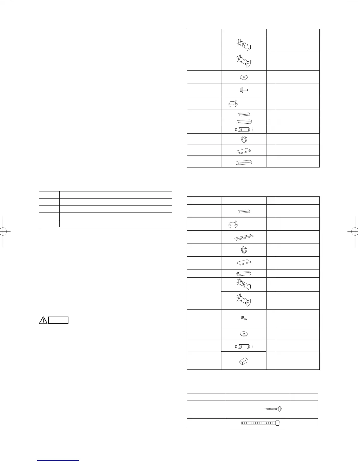
1-2. Accessories Supplied with Unit
See Tables 1-1 to 1-4.
Table Type
1-1 1-Way Cassette
1-2 2-Way Cassette
1-3 Wall Mounted
1-4 Floor Standing & Concealed Floor Standing
1-3. Type of Copper Tube and Insulation Material
If you wish to purchase these materials separately from a local
source, you will need:
1. Deoxidized annealed copper tube for refrigerant tubing.
Cut each tube to the appropriate lengths +30 cm to 40 cm
to dampen vibration between units.
2. Foamed polyethylene insulation for copper tubes as
required to precise length of tubing. Wall thickness of the
insulation should be not less than 8 mm.
3. Use insulated copper wire for field wiring. Wire size varies
with the total length of wiring.
Refer to 4. ELECTRICAL WIRING for details.
CAUTION
Check local electrical codes and regulations before
obtaining wire. Also, check any specified instructions or
limitations.
1-4. Additional Materials Required for Installation
1. Refrigeration (armored) tape
2. Insulated staples or clamps for connecting wire (See your
local codes.)
3. Putty
4. Refrigeration tubing lubricant
5. Clamps or saddles to secure refrigerant tubing
6. Scale for weighing
Table 1-1 (1-Way Cassette)
Part Name Figure
Q
’
ty
Remarks
Installation
gauge (Use the
packaging side
pad.)
1
Gauge A (Install on
tubing side.)
1
Gauge B (Install
on opposite side of
tubing.)
Washer
8
Suspension brackets,
upper/lower
Screw
4
For full-scale
installation diagram
Insulating tape
(White)
2
For gas and liquid
tube flare nuts
Flare insulator
1
For liquid tubes
1 For gas tubes
Drain hose
1
For drain joint
Hose band
1
For drain joint
Packing
1
For drain joint
Drain insulator
1 For drain joint
●
Use 3/8" or M10 for suspending bolts.
●
Field supply for suspending bolts and nuts.
Table 1-2 (2-Way Cassette)
Part Name Figure
Q
’
ty
Remarks
Flare insulator
2
For gas and liquid
tubes
Insulating tape
(White)
2
For gas and liquid
tube flare nuts
Vinyl clamp
8
For flare insulator
and drain insulator
Hose band
1
For securing drain
hose
Packing
1
For drain joint
Drain insulator
1
For drain joint
Installation
gauge (Use the
packaging side
pad.)
1
Gauge A (Install on
tubing side.)
1
Gauge B
(Install on opposite
side of tubing.)
M5 × L40
(Black screw,
with washer)
4
For fastening
installation gauges
Special washer
8
For suspension bolts
Drain hose
(L = 25cm)
1
For securing drain
hose
Putty
1
For sealing
recessed portion of
power supply
Table 1-3 (Wall Mounted)
22, 28, 36 types
Part Name Figure Q’ty
Tapping screw
Truss-head
Phillips
4 × 30 mm
8
Clamp
1
PanaIndoor-337012Eng.indb6PanaIndoor-337012Eng.indb6 2012/03/2116:20:432012/03/2116:20:43
 Loading...


