19
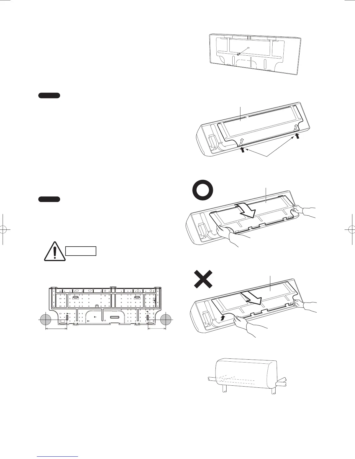
Set screw only for transportation
Fig. 3-71
Fig. 3-72
Fig. 3-73
Fig. 3-74
Fig. 3-75
Rear panel
■ Wall Mounted Type (K1 Type)
45, 56, 73, 106 types
3-20. Remove the Rear Panel from the Unit
(1) Remove and discard the set screw on the rear panel.
(Fig. 3-71)
(2) Press the 2 U marks on the frame cover and disengage
the stationary tabs from the frame. (Fig. 3-72)
(3) Remove the rear panel by grasping the sections shown in
Fig. 3-73 and pulling it in the direction shown by the arrow.
NOTE
Tubing can be extended in 6 directions as shown in Fig. 3-75.
Select the direction you need providing the shortest run to the
outside unit.
● When left tubing is to be done, switch the drain hose and
drain cap. (For details, refer to “Switching drain hose and
drain cap” on page 24.)
3-21. Make a Hole
(1) Place the rear panel from the indoor unit on the wall at the
location selected. Make sure the panel is horizontal, using
a carpenter’s level or tape measure to measure down from
the ceiling. Wait until after cutting the hole before attaching
the rear panel to the wall.
(2) Determine which side of the unit you should make the hole
for tubing and wiring. (Fig. 3-76)
NOTE
In the case of left-rear tubing, use the measurement points
158 mm from the marked position on the rear panel for precise
placement of the hose outlet. (Fig. 3-76)
(3) Before making the hole, check carefully that no studs or
pipes are directly run behind the spot to be cut.
CAUTION
Also avoid areas where
electrical wiring or conduits
are located.
The above precautions are also applicable if tubing goes
through the wall in any other location.
Fig. 3-76
U marks
Rear panel
Rear panel
Left tubing
Left-rear
tubing
Left-downward tubing
Right-downward tubing
Right tubing
Right-rear tubing
(recommended)
158 mm 132 mm
Unit: mm
PanaIndoor-337012Eng.indb19PanaIndoor-337012Eng.indb19 2012/03/2116:20:482012/03/2116:20:48
 Loading...


