Approx. 120 seconds with C-60 cassette tape
■ DISC SECTION
Disc played [8 cm or 12 cm]
(1) CD-Audio (CD-DA)
(2) CD-R/RW (CD-DA, MP3* formatted disc)
(3) MP3*
* MPEG-1 Layer 3, MPEG-2 Layer 3
Pick up
Wavelength 780 nm
Beam Source Semiconductor laser
Audio output (Disc)
Number of channel 2.1 (FL, FR, SW)
FL = Front left channel
FR = Front right channel
SW = Subwoofer channel
■ USB SECTION
USB Port
USB Standard USB 2.0 full speed
Media file format support
MP3 (*.mp3)
USB device file system
FAT 12
FAT 16
FAT 32
USB port power 500 mA (Max)
USB Ripping (recording)
Recording file format
MP3 (*.mp3)
Bit rate 128 kbps / 192 kbps / 320 kbps
1 Safety Precautions
3
2 Prevention of Electro Static Discharge (ESD) to
Electrostatically Sensitive (ES) Devices
5
3 Handling Precautions for Traverse Unit
6
4 Precaution of Laser Diode
8
5 About Lead Free Solder (PbF)
9
6 Operation Procedures
10
7 Self diagnosis and special mode setting
14
8 Assembling and Disassembling
22
9 Disassembly and Assembly of Traverse Unit Assembly in
Play Position
58
10 Service Fixture and Tools
60
11 Service Positions
60
USB recording speed 1x, max 4x (CD only)
■ GENERAL
Power supply
AC 120 V, 60Hz (PL only)
AC 110 to 127/220 to 240 V, 50/60 Hz (GCP only)
Power consumption 164W(PLOnly)
145 W (GCP Only)
Dimensions (WxHxD) 250 x 331 x 334 mm
Mass 4.9 kg
Operating temperature range 0 to 40°C
Operating humidity range 35 to 80% RH (no condensation)
Power consumption in standby mode:
0.3 W (approx.) (PL only)
0.5 W (approx.) (GCP only)
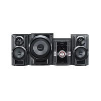
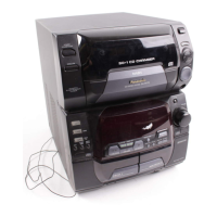
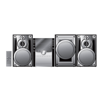
■ SYSTEM
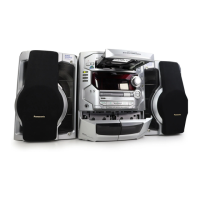
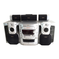
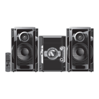
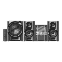
SC-AK770 (PL) Music center: SA-AK770 (PL)
Speakers: SB-AK770 (PL)
Subwoofer: SB-WAK770 (PL)
SC-AK770 (GCP) Music center: SA-AK770 (GCP)
Speakers: SB-AK770 (PL)
Subwoofer: SB-WAK770 (PL)
For information on speaker system, please refer to the original
Service Manual (Order No. MD0805008CE) for SB-AK770PL-K &
(Order No. MD0805009CE) for SB-WAK770PL-K.
Notes:
1. Specifications are subject to change without notice. Mass and
dimensions are approximate.
2. Total harmonic distortion is measured by the digital spectrum
analyzer.
12 Procedure for Checking Operation of Individual Parts of Deck
Mechanism Unit
68
13 Measurement And Adjustments
69
14 Voltage Measurement and Waveform Chart
71
15 Wiring Diagram
79
16 Block Diagram
81
17 Notes Of Schematic Diagram
89
18 Schematic Diagram
91
19 Printed Circuit Board
109
20 Illustration of ICs, Transistors and Diodes
117
21 Terminal Function of Integrated Circuits
118
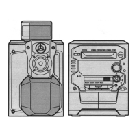
22 Exploded Views
121
23 Replacement Parts List
125
CONTENTS
Page Page
2