(All schematic diagrams may be modified at any time with
the development of new technology)
Notes:
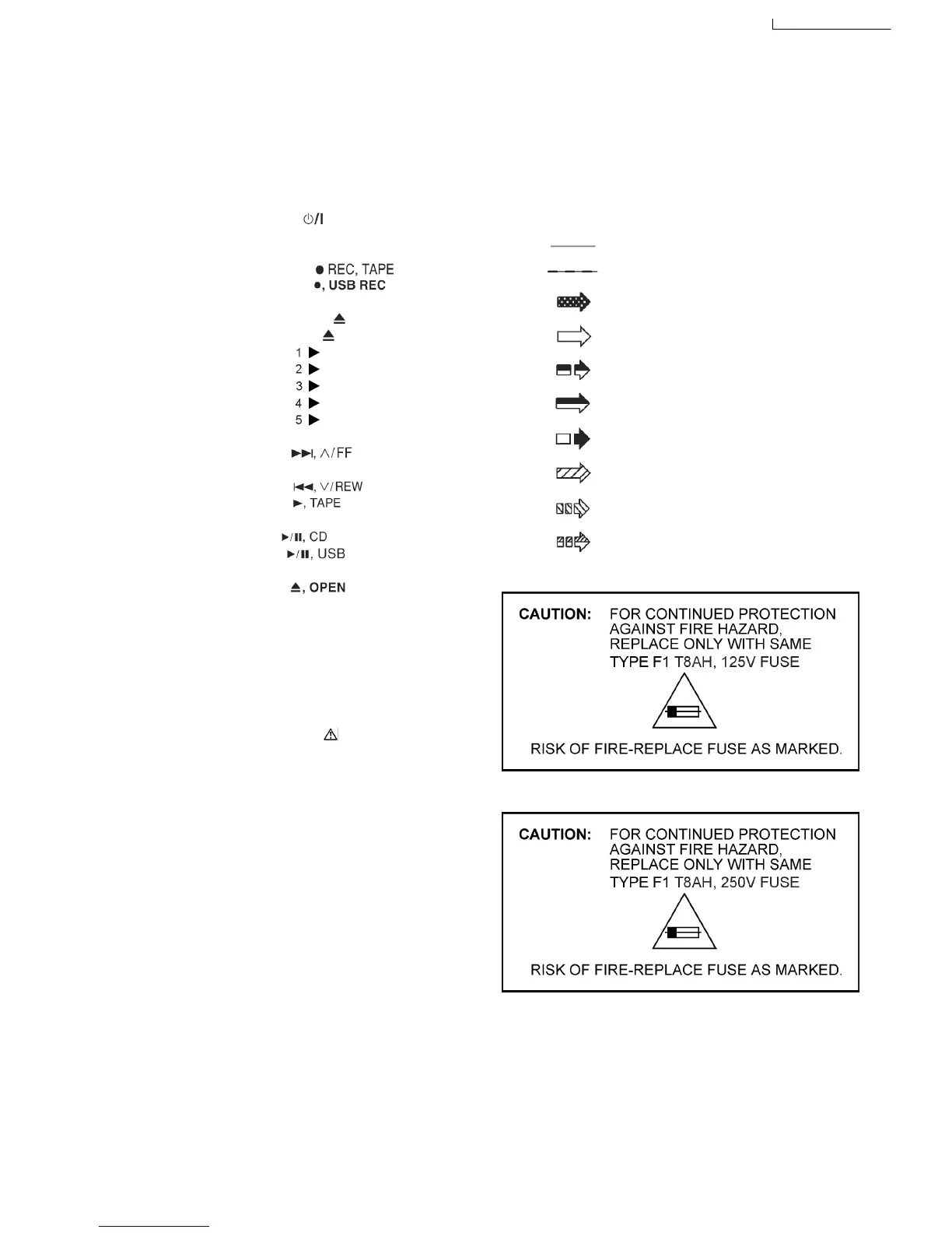
S971: Mode switch.
S972: Half switch.
S975: Recinh_F switch.
S5701: Voltage Selector switch (For GCP
Only).
S6100: Power (
) switch.
S6101: Display switch.
S6102: Subwoofer switch.
S6106: Tape Rec (
) switch.
S6107: USB Rec (
) switch.
S6108: D.Bass switch.
S6201: Open/Close (
) switch.
S6202: Exchange (
) switch.
S6203: CD1 (
) switch.
S6204: CD2 (
) switch.
S6205: CD3 (
) switch.
S6206: CD4 (
) switch.
S6207: CD5 (
) switch.
S6208: Stop/Demo switch.
S6300: FWD (
) switch.
S6301: Manual_EQ switch.
S6302: REW (
) switch.
S6303: Tape (
) switch.
S6304: FM/AM switch.
S6306: CD (
) switch.
S6307: USB (
) switch.
S6308: EXT_IN switch.
S6820: Eject (
) switch.
S7201: Rest switch.
S7202: CD Open switch.
VR6500: VR Volume.
VR6630: VR Bass Control.
VR6701: VR Mic Volume.
• Importance safety notice :
Components identified by
mark have special
characteristics important for safety.
Furthermore, special parts which have purposes of fire-
retardant (resistors), high-quality sound (capacitors), low-
noise (resistors), etc. are used.
When replacing any of components, be sure to use only
manufacturer´s specified parts shown in the parts list.
• In case of AC rated voltage Capacitor, the part no. and
values will be indicated in the Schematic Diagram.
AC rated voltage capacitor:
C5700, C5701, C5703, C5704, C5705, C5706 (FOR GCP
ONLY), C5707(FOR GCP ONLY)
• Resistor
Unit of resistance is OHM [Ω] (K=1,000).
• Capacitor
Unit of resistance is µF, unless otherwise noted. F=Farad,
pF=Pico-Farad
• Coil
Unit of inductance is H, unless otherwise noted.
• *
FOR INDICATION ONLY.
• Voltage and Signal lines:
: +B Signal line
: -B Signal line
: CD DA signal line
: CD signal line
: Tape Record signal line
: Tape Playback signal line
: FM/AM signal line
: Main signal line
: AUX/Mic/Music Port signal line
: USB signal line
• PL only
• GCP only
17 Notes Of Schematic Diagram
89



 To Next Page