16
RQT8739
Connections
The component video terminals can produce more accurate colors than the S video terminals (á page 15).
Connection cable (All cables are sold separately)
• The input video signal can be sent out through an output terminal of the same type only.
• See page 19 for connecting the unit to a cable box or satellite receiver.
Connecting cables to component and audio terminals (to use the TV and DVD recorder)
Video cable Audio cable
Video connection cable
Optical fiber cable
(CD)
S VIDEO
VIDEO
L
R
CD DVD 6CH IN
SUBWOOFER
BD/DVD/ VCR TV/STB
FRONTA FRONTB CENTER SURROUND
SURROUND BACK
Y
TV MONITOR OUT TV / STB INDVD RECORDER IN
PB PR
SPEAKERS
COMPONENT VIDEO
HAUT-PARLEURS
Y YPB PR PB PR
AC IN
RL RL RLRL
BI-WIRE
LF HF
AUDIO
DIGITAL IN
DIGITAL TRANSCEIVER
(BD/
DVD PLAYER)
(DVD RECODER)
(TV/STB)
OPTICAL1 OPTICAL2
COAXIAL1 COAXIAL2
XM
LOOP EXT
GND
LOOP
GND
LOOP
GND
AM ANTFM ANT
LOOP ANT
GND
(BD/DVD PLAYER) IN
OUT
OUT
OUT
IN IN
IN IN IN IN
OUT
SUBWOOFER SURROUND
FRONT
IN IN IN IN IN
TV/STBVCR
DVD RECORDER
DVD RECORDER
DVD RECORDER
TV MONITORTV MONITOR
TV/STB
CENTER
BD/
DVD PLAYER
BD/
DVD PLAYER
(DVD RECORDER) IN
YPB PR
YPB PR
TV
COMPONENT
VIDEO OUT
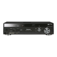
Rear panel
“Changing the digital input
settings” (á page 37)
• To enjoy TV with surround sound,
make additional connections
instructed on page 17.
DIGITAL
AUDIO OUT
(OPTICAL)
DVD recorder
COMPONENT
VIDEO IN
Component video terminals
The component video terminals (color-difference video terminals) output red (PR), blue (PB), and luminance (Y) signals
separately. The terminals reproduce colors with greater accuracy for this reason.
Insert the cable after
making sure shapes
match.
How to connect the optical
fiber cable
Do not sharply bend the
optical fiber cable.
Note
 Loading...