This unit is designed to operate on power supplied from system connected.
When a component requires service, use the system connections to supply power
source.
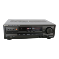
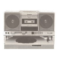
For system connections, refer to
Fig.9-1.
Fig. 9-1.
10. Schematic Diagram Notes
- This schematic diagram may be modified at any time with the development of new
technology.
Notes:
S901:
Power standby/on switch (
)
S902:
Select switch (SELECT)
VR901:
Volume control VR (VOLUME)
- Indicated voltage values are the standard values for the unit measured by the DC
electronic circuit tester (high-impedance) with the chassis taken as standard.
Therefore, there may exist some errors in the voltage values, depending on
theinternal impedance of the DC circuit tester.
No mark
: Power ON (FM or AM)
- Important safety notice:
Components identified by
mark have special characteristics important for
27
 Loading...