Flow-Chart for Disassembly Procedure
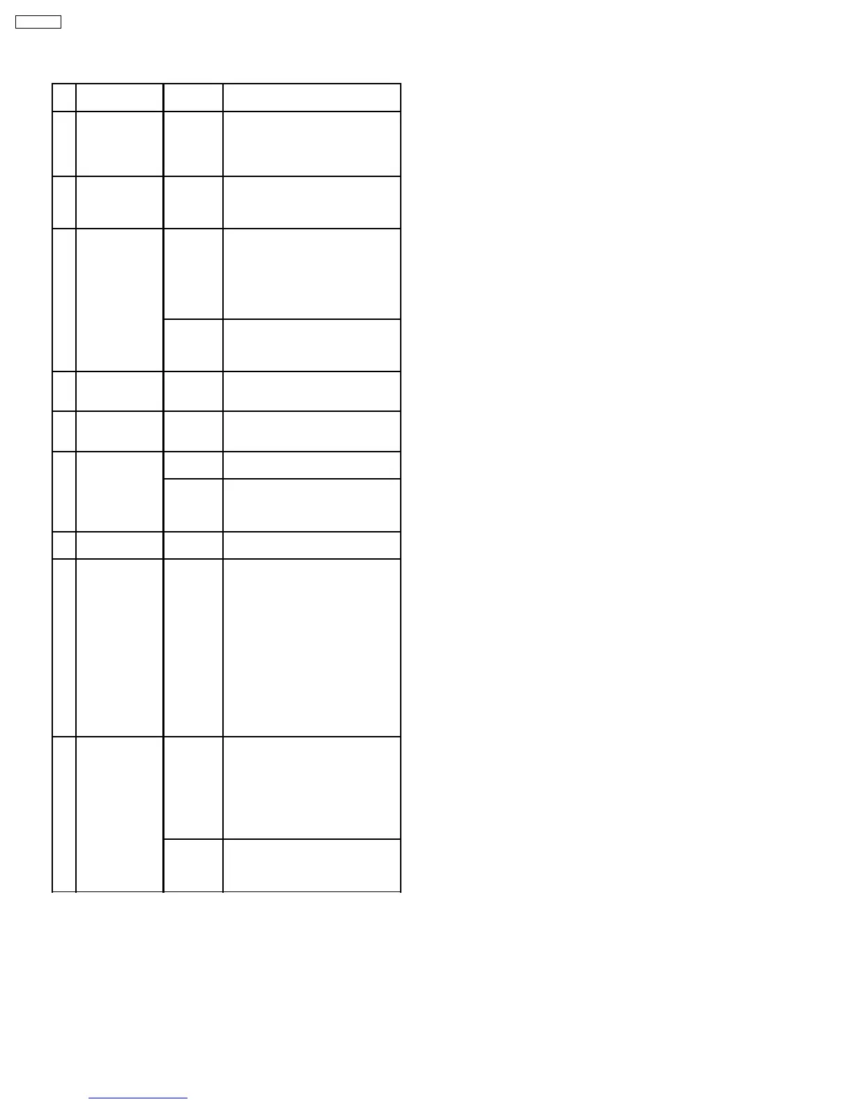
No. Item / Part Fig. Removal (Screw,Connector,FPC.
& Other)
1 Rear Case Unit Fig. D2 Open the LCD Unit and Jack
Cover.
7-Screws (A)
1-Connector FP11
Rear Case Unit
2 Operation Unit Fig. D3 2-Screws (B)
4-Tabs
1-Connector FP61
Operation Unit
3 Front/ Top Case
Unit
Fig. D4 4-Hooks
1-Connector P2502
Hard Disk Drive, HDD Cushion,
Top Case
3-Screws (C)
1-Connector B21
HDD Relay P.C.B.
Fig. D5 3-Screws (D), 2-Screw (E)
1-Tab
2-Connectors FP63, FP6501
Front/ Top Case Unit
4 Side R/ LCD
Unit
Fig. D6 1-Screw (F)
2-Connectors FP62, FP81
Side R/ LCD Unit
5 Lens Unit Fig. D7 1-Screw (G)
3-Connectors FP31, FP71, FP72
Lens Unit
6 Main P.C.B. Fig. D8 1-Screw (H)
Bottom Angle Unit
Fig. D9 1-Screw (I), 1-Screw (J)
Main Shield Plate A
2-Screws (K)
Main P.C.B.
7 Front P.C.B. Fig. D10 4-Screws (L)
Front Earth Angle, Front P.C.B.
8 Open Switch/
Side R P.C.B.
Fig. D11 2-Screws (M)
Speaker Fixing Angle
1-Connector P6301
Speaker
5-Screws (N)
Open Switch P.C.B., Side R
P.C.B.
Note:
When fixing the Open SW P.C.B.
and Side R P.C.B., open the LCD
Unit and SD Cover. If you fix them
without opening, both the Open
SW (SW8301) and SD Det. SW
(SW6305) will be damaged.
9 LCD B/L P.C.B. Fig. D12 Turn the LCD Case to the arrow
direction so that the screws can
be seen, and remove the 2
screws (O).
6-Tabs
LCD Case (Upper)
1-Connector FP8101
LCD Case (Lower) Unit
Fig. D13 1-Connector FP8102
1-Screw (P)
3-Tabs
LCD B/L P.C.B.
8.3. Disassembly Procedures
30
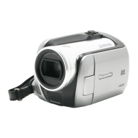
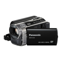
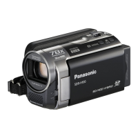
SDR-H20E
 Loading...