12
15. DeviceNet SIDE SETTING
VendCode = 90; $Vendor Code
ProdType = 12; $Product Type
ProdCode = 7 ; $Product Code
VendTypeStr = “hms Fieldbus Systems AB(Hassbje”;
ProdName = “ABDTDEV”
I/O byte No. setting
When SL-GU1-D is incorporated into the DeviceNet system, the data exchange size on De-
viceNet is determined by the setting on the S-LINK system side.
Secure a memory area on the master depending on the total No. of I/O, I/O setting and sta-
tus setting of the S-LINK system side.
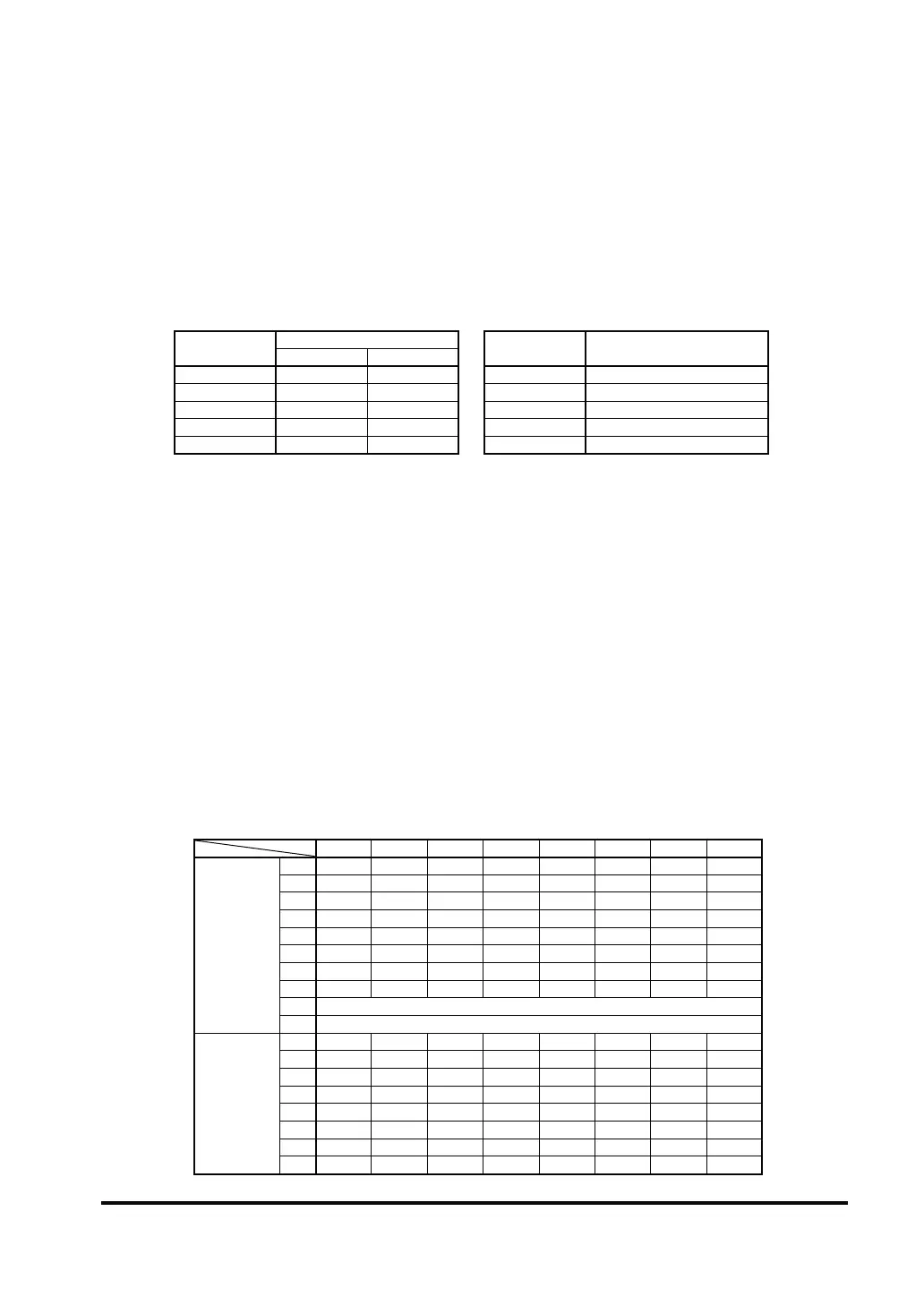
Required No. of bytes for each switch setting
Total No. of in-
put channels
No. of byte
Total No. of out-
put channels
No. of byte
Without status With status
002 0 0
32 4 6 32 4
64 8 10 64 8
96 12 14 96 12
128 16 18 128 16
Example: In case of S-LINK I/O units = 128 Nos., input: 64 Nos., output: 64 Nos., and with status added
Required No. of bytes for input data = 10 bytes
Required No. of bytes for output data = 8 bytes
16. MEMORY MAP
Transmission / Reception I/O data, status data
lowest address (00H), is as given below
Reception I/O data area : Input data area + Status data area
Transmission I/O data area: Output data area
I/O data assignment for S-LINK unit address
The S-LINK addresses are organized linearly and each S-LINK unit can be assigned I/O set-
ting in units of 32.
Further, the upper level transmission / reception I/O data is divided into input data and output
data, assigned and transmitted, and organized continuously from the lowest position.
As an example, the memory assignment for the case of I/O channels: 128 Nos., input setting:
Address 0 to 63, output setting: Address 64 to 127, and with status data is shown below.
(In this case, the upper side data size is input: 10 bytes, output: 8 bytes.)
Bit 7 Bit 6 Bit 5 Bit 4 Bit 3 Bit 2 Bit 1 Bit 0
Reception I/O
data area
00H76543210
01H 15 14 13 12 11 10 9 8
02H 23 22 21 20 19 18 17 16
03H 31 30 29 28 27 26 25 24
04H 39 38 37 36 35 34 33 32
05H 47 46 45 44 43 42 41 40
06H 55 54 53 52 51 50 49 48
07H 63 62 61 60 59 58 57 56
08H
09H Status data (error address)
Transmission
I/O data area
00H 71 70 69 68 67 66 65 64
01H 79 78 77 76 75 74 73 72
02H 87 86 85 84 83 82 81 80
03H 95 94 93 92 91 90 89 88
04H 103 102 101 100 99 98 97 96
05H 111 110 109 108 107 106 105 104
06H 119 118 117 116 115 114 113 112
07H 127 126 125 124 123 122 121 120
 Loading...