2
3. FUNCTIONAL DESCRIPTION
1
2
3
4
10
11
12
13
5
6
7
8
9
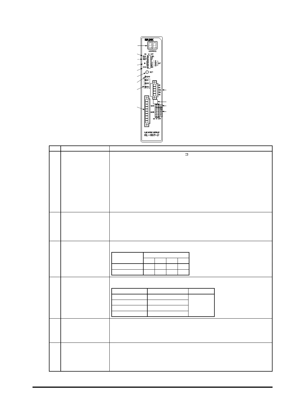
No. Designation Description
1
Address display
(ADDRESS) (Red)
During normal transmission, a rotating “ ” character is displayed.
Further, depending upon the setting of the S-LINK system output condition in case of
abnormality in the upper network, decimal points light up.
All outputs reset to “OFF”: Decimal points off
All outputs maintained: Decimal points light up
Immediately after pressing the system set button, the number of recognized connected
-
nized unit addresses are displayed.
In case Error 4 occurs, the smallest unit address where the error occurs is displayed
in hexadecimal form. In case the error occurs at several units, the decimal points also
light up.
In the check mode, all the unit addresses where the error occurs are displayed in the
ascending order.
2 Mode switch (RUN/CHK.)
It sets the operating condition of SL-GU1-D.
RUN: Operation mode
Set for normal operation.
CHK.: Check mode
SL-GU1-D, or, when Error
3
I/O channel No. control
switch (SYS.ADD.)
It sets the No. of S-LINK I/O channels.
I/O channel No. setting
I/O channel No.
control switch
I/O channel No.
32 64 96 128
B0 OFF ON OFF ON
B1 OFF OFF ON ON
4 I/O setting switch
It sets the I/O of the S-LINK system.
I/O setting
I/O setting switch S-LINK unit address I/O setting
IN/OUT 0 to 31 0 to 31
Input: ON
Output: OFF
IN/OUT 32 to 63 32 to 63
IN/OUT 64 to 95 64 to 95
IN/OUT 96 to 127 96 to 127
5
Status setting switch
(STAT./OFF)
STAT.: Status mode
Error information, etc., of the S-LINK system side is added as status data (2 byte) to
the DeviceNet transmission data.
OFF:
Status data is not added to the DeviceNet transmission data.
6
System set button
(SET)
If the power supply of SL-GU1-D is switched on when the system set button is pressed,
the setting of the S-LINK system side output in case of upper network abnormality is
changed.
It is pressed to make SL-GU1-D recognize the unit addresses in the S-LINK system.
In the check mode, it becomes the button for displaying the addresses of the recog-
nized units or the faulty units.
 Loading...