EasyManua.ls Logo

Panasonic SU-HTB550GK

Panasonic SU-HTB550GK
154 pages
To Next Page IconTo Next Page
Loading...
© Panasonic Corporation 2012. All rights reserved.
Unauthorized copying and distribution is a violation of
law.
PSG1206002CE
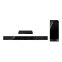
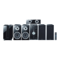
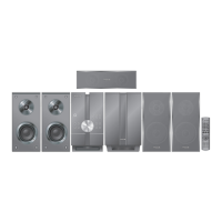
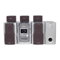
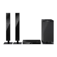
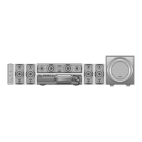
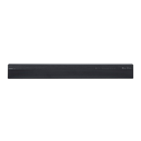
Home Theater Audio System
Model No. SU-HTB550GK
SU-HTB550GS
SU-HTB550GSX
SB-HTB550P
SB-HTB550GK
SB-HWA520GK
SB-HWA520GS
SB-HWA520GSX
SC-HTB550GK
SC-HTB550GS
SC-HTB550GSX
Product Color: (K)...Black Type
TABLE OF CONTENTS
PAGE PAGE
1 Safety Precautions----------------------------------------------- 3
1.1. General Guidelines---------------------------------------- 3
1.2. Before Repair and Adjustment ------------------------- 4
1.3. Protection Circuitry ---------------------------------------- 4
1.4. Caution For Fuse Replacement------------------------ 4
1.5. Caution For SMPS Module------------------------------ 4
1.6. Caution for the AC Mains Lead (For GS only) ----- 5
1.7. Safety Part Information -----------------------------------6
1.8. Safety Installation Instructions -------------------------7
2Warning--------------------------------------------------------------8
2.1. Prevention of Electro Static Discharge (ESD)
to Electrostatically Sensitive (ES) Devices ----------8
2.2. Service caution based on Legal restrictions --------9
3 Service Navigation --------------------------------------------- 10

Table of Contents

Questions and Answers:

Panasonic SU-HTB550GK Specifications

General IconGeneral
BrandPanasonic
ModelSU-HTB550GK
CategoryHome Cinema speakers
LanguageEnglish

Summary

Safety Precautions

General Guidelines

General safety advice for servicing, including leakage current checks.

Leakage Current Checks

Procedures for checking leakage current to prevent shock hazards.

Warning

Electro Static Discharge (ESD) Prevention

Protecting sensitive components from ESD during handling and repair.

Service Cautions based on Legal Restrictions

Cautions for repair work, including lead-free solder guidelines.

Service Navigation

Service Information

Overview of service manual content and procedures for ordering parts.

Specifications

General Introduction

About VIERA Link

Explanation of VIERA Link feature for system control and connectivity.

Location of Controls and Components

Main Unit Controls

Description of buttons, indicators, and terminals on the main unit.

Indicator Illumination

Explanation of system status indicated by LEDs during operation.

Remote Control Operations

Functions of buttons on the remote control for system operation.

Installation Instructions

Connections Overview

Guide for connecting the system to TV and other audio/video devices.

Service Mode

Service Mode Procedures

Steps to enter and use service modes for diagnostics and settings.

Displayed Error Codes

Troubleshooting using LED blinking patterns to identify system errors.

Troubleshooting Guide

Service Fixture & Tools

Disassembly and Assembly Instructions

Disassembly Flow Charts

Visual guide to disassembling the main unit, speakers, and subwoofer.

Main Unit Disassembly Procedures

Step-by-step instructions for disassembling the main unit's components.

Front Speaker Disassembly Procedures

Step-by-step instructions for disassembling the front speaker units.

Active Subwoofer Disassembly Procedures

Step-by-step instructions for disassembling the active subwoofer.

Service Position

Main Unit Service Positions

Procedures for checking and repairing main unit PCBs (Side A and B).

Active Subwoofer Service Positions

Procedures for checking and repairing active subwoofer PCBs.

Block Diagrams

Overall Control Diagram

Simplified block diagram showing system architecture and data flow.

Power Supply Diagram

Diagram illustrating the power supply stages and voltage distribution.

Block Diagrams

System Control Block Diagram

Detailed block diagram of the system's control logic.

HDMI Block Diagram

Diagram illustrating the HDMI signal path and components.

Audio Block Diagram

Diagram showing the audio signal path and processing.

Power Supply Block Diagrams

Detailed diagrams of the power supply circuits (1/2 and 2/2).

Wiring Connection Diagram

Main Unit Wiring

Diagram showing internal wiring connections for the main unit.

Active Subwoofer Wiring

Diagram showing internal wiring connections for the active subwoofer.

Schematic Diagrams

Schematic Diagram Notes

Key for symbols, lines, and component notations used in schematics.

Main Unit Schematics

Detailed circuit diagrams for the main unit's various sections.

Active Subwoofer Schematics

Detailed circuit diagrams for the active subwoofer's sections.

Printed Circuit Board Layouts

Main Unit PCB Layouts

Visual representation of component placement on main unit PCBs.

Active Subwoofer PCB Layouts

Visual representation of component placement on subwoofer PCBs.

Appendix: Voltage & Waveform Data

Main Unit Voltage Measurements

Standard voltage values for key points on the main unit PCBs.

Waveform Charts

Visual representations of signal waveforms at specific test points.

Exploded View and Parts Lists

Mechanical Parts Lists

Lists of mechanical components and their part numbers for replacement.

Electrical Parts Lists

Lists of electrical components and their part numbers for replacement.

Related product manuals