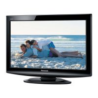
45
Secondary Power Supply Check
Confirm that the P board is good.
Check the IC1106 on
Circuit Board DG and
IC7501 on Circuit Board
RD.
NG
1) Confirm the power control signals from IC1106.
MAIN_ON: (H) 2.4V, (L) 0V: Pin 39 of PAP2
SUB_ON
PANEL_O ) 2.4V, (L) 0V: Pin 23 of
2 50
AP6
of
PAP6
OK
: (H) 2.4V, (L) 0V: Pin 38 of PAP2
N: (H
PAP2
) Confirm the power control signals from IC7
P_ON_H: (H) 5V, (L) 0V Pin 15 of P
DR_P_ONH: (H) 5V, (L) 0V: Pin 16
1.
Check the R858, 860,
870, 871, 872, 859,
861,873, 874, 899, D841
and D842.
NG
OK
Confirm the voltage at R870 and R873. (3V)
NG
C regula
0V
(L) 0V
PANEL_ACT: (H) 2.4V, (L) 0V
DR_P_ON T: (H) 2.4V, (L) 0V
P_ON_ACT: (H) 2.4V, (L) 0V
OK
onfirm the power control signals to each
MAIN_ACT: (H) 2.4V, (L)
SUB_ACT: (H) 2.4V,
tor.
_AC
OK
Confirm the output voltage from
each regulator IC.
NG
Replace the Regulator
IC.
OK
There is no problem in Circuit Board AP
C sistor.
6
PANEL_ACT: D835, D858
DR_P_ON_ACT: D834, D860,
Q828
P_ON_ACT: D831, D859, Q827
heck the each Diode and Tran
MAIN_ACT: D830, D85
SUB_ACT: D832, D857
 Loading...