EasyManua.ls Logo

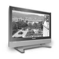
Panasonic TH-103PF10WK - User Manual

Panasonic TH-103PF10WK
126 pages
To Next Page IconTo Next Page
Loading...
© 2007 Matsushita Electric Industrial Co., Ltd. All
rights reserved. Unauthorized copying and distribu-
tion is a violation of law.
Order Number ITD0711079CE
High Definition Plasma Display
Model No. TH-103PF10WK
Model No. TH-103PF10TK
Model No. TH-103PF10RK
GPF10D Chassis
TABLE OF CONTENTS
PAGE PAGE
1 Safety Precautions----------------------------------------------- 3
1.1. General Guidelines---------------------------------------- 3
2 Warning -------------------------------------------------------------- 4
2.1. Prevention of Electrostatic Discharge (ESD)
to Electrostatically Sensitive (ES) Devices---------- 4
2.2. About lead free solder (PbF)---------------------------- 5
3 Service Navigation ----------------------------------------------- 6
3.1. Service Hint ------------------------------------------------- 6
3.2. Applicable signals ----------------------------------------- 8
4 Specifications ----------------------------------------------------10
5 Service Mode -----------------------------------------------------11
5.1. CAT (Computer Aided Test) mode -------------------11
5.2. IIC mode structure (following items value is
sample data) -----------------------------------------------15
5.3. Option Setting ---------------------------------------------16
6 Troubleshooting Guide ----------------------------------------18
6.1. Self Check--------------------------------------------------18
6.2. No Power ---------------------------------------------------20
6.3. No Picture --------------------------------------------------20
6.4. Local screen failure --------------------------------------21
7 Disassembly and Assembly Instructions ---------------22
7.1. Rear Cover and Board ----------------------------------22
7.2. Location of Rear Cover screws -----------------------23
7.3. Removal of Side Angle (L), (R) -----------------------26
7.4. Removal of HA-Board -----------------------------------27
7.5. Removal of HDMI-Board ------------------------------ 28
7.6. Removal of DS-Board ---------------------------------- 28
7.7. Removal of HX-Board----------------------------------- 28
7.8. Removal of DN-Board ---------------------------------- 29
7.9. Removal of PB-Board----------------------------------- 29
7.10. Removal of H5-Board ----------------------------------- 29
7.11. Removal of D-Board ------------------------------------ 30
7.12. Removal of P-Board (MULTI_1), (MULTI_2) ------ 30
7.13. Removal of P-Board (SUS_1), (SUS_2) ----------- 31
7.14. Removal of F-Board ------------------------------------ 31
7.15. Removal of PC-Board ---------------------------------- 31
7.16. Removal of SU-Board ---------------------------------- 32
7.17. Removal of SM-Board ---------------------------------- 33
7.18. Removal of SD-Board ---------------------------------- 33
7.19. Removal of SC-Board --------------------------------- 34
7.20. Removal of SC2-Board -------------------------------- 35
7.21. Removal of S1-Board and V2-Board---------------- 35
7.22. Removal of SS2-Board -------------------------------- 36
7.23. Removal of SS3-Board -------------------------------- 36
7.24. Removal of SS-Board ---------------------------------- 37
7.25. Removal of Fan------------------------------------------- 38
7.26. Removal of C1-Board ----------------------------------- 39
7.27. Removal of C2-Board ----------------------------------- 39
7.28. Removal of C3-Board ----------------------------------- 40
7.29. Removal of C4-Board ----------------------------------- 41

Table of Contents

Question and Answer IconNeed help?

Do you have a question about the Panasonic TH-103PF10WK and is the answer not in the manual?

Panasonic TH-103PF10WK Specifications

General IconGeneral
Screen Size103 inches
Resolution1920 x 1080 pixels
Panel TypePlasma
Aspect Ratio16:9
Input TerminalsHDMI, Component, Composite, S-Video

Summary

Safety Precautions

General Guidelines

General guidelines for conducting repairs and servicing safely.

Warning

Prevention of Electrostatic Discharge (ESD)

Techniques to prevent damage to sensitive electronic components from static discharge.

About Lead Free Solder (PbF)

Service Navigation

Service Hint

Hints for servicing the plasma unit, including setup for servicing.

Specifications

Service Mode

CAT (Computer Aided Test) Mode

Guide to accessing and using the Computer Aided Test (CAT) mode for diagnostics.

IIC Mode

Steps to access and exit the IIC mode within the CAT mode.

CD Mode

Instructions for accessing and using the CD mode in CAT for microcomputer software.

SD Mode

Instructions for accessing and using the SD mode in CAT for diagnostic purposes.

MS Mode

ID Mode

IIC Mode Structure

Option Setting

Troubleshooting Guide

Self Check

Information on the self-check function and display indications for troubleshooting.

Power LED Blinking Timing Chart

Chart detailing power LED blinking patterns to identify specific faults.

No Power Troubleshooting

Troubleshooting steps for when the unit does not power on, based on LED status.

No Picture Troubleshooting

Troubleshooting flowchart for issues related to the display showing no picture.

Local Screen Failure

Disassembly and Assembly Instructions

Rear Cover and Board Removal

Instructions on how to remove the rear cover to access various boards for replacement.

Removal of Rear Cover (A)

Step-by-step guide to remove the rear cover section labeled 'A'.

Removal of Side Angles

Removal of Side Angle (L)

Instructions for removing the left side angle component.

Board Removal: HA-Board

Board Removal: HDMI-Board

Board Removal: DN-Board

Board Removal: D-Board

Board Removal: P-Board (SUS;MULTI)

Board Removal: SU-Board

Board Removal: SD-Board

Board Removal: SC-Board

Board Removal: S1-Board and V2-Board

Removal of S1-Board

Instructions for removing the S1-Board.

Removal of V2-Board

Board Removal: SS-Board

Fan Removal

Board Removal: C1-Board

Board Removal: C3-Board

Board Removal: C4-Board

Board Removal: C6-Board

Board Removal: C8-Board

Board Removal: CX-Board

Board Removal: CZ-Board

Board Removal: DR1-Board (A;B)

Board Removal: CD-Board (A-F)

AC Inlet Removal

Plasma Panel Removal

Measurements and Adjustments

Adjustment Procedure

General procedure for performing voltage adjustments on the driver section.

Driver Adjustments

Details the specific voltage adjustments to be made in the driver section.

Initialization Pulse Adjustment

PCB Replacement Adjustments

RGB White Balance Adjustment

HD White Balance Adjustment

Power Control Adjustment

Block Diagrams

Diagram Notes

Notes and explanations regarding the block diagrams presented in the manual.

Main Block Diagram (1 of 2)

Main Block Diagram (2 of 2)

P-Board and F-Board Block Diagram

HA, HX, PC, PB, V1, V2 and V3-Board Block Diagrams

HDMI-Board Block Diagram (1 of 2)

DS-Board and H3-Board Block Diagram (1 of 2)

DN-Board Block Diagram (1 of 2)

D-Board Block Diagram (1 of 2)

C1, C2, CY and CZ-Board Block Diagrams

C4, C5, C8 and C9-Board Block Diagrams

SC2 and S1-Board Block Diagram

SC-Board Block Diagram

SU, SM and SD-Board Block Diagrams

SS, SS2 and SS3-Board Block Diagrams

DR1, DR2 and CD-Board Block Diagrams

Wiring Connection Diagram

Interconnection (1 of 8)

Diagram showing wiring interconnections between major boards (part 1 of 8).

Interconnection (2 of 8)

Diagram showing wiring interconnections between major boards (part 2 of 8).

Interconnection (3 of 8)

Diagram showing wiring interconnections between major boards (part 3 of 8).

Interconnection (4 of 8)

Diagram showing wiring interconnections between major boards (part 4 of 8).

Lead Wiring Diagram

Related product manuals