93
English
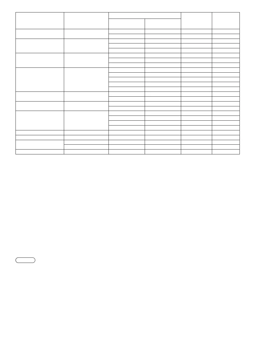
Corresponding signal Resolution (Dot)
Scanning frequency Dot clock
frequency
(MHz)
Format
*
3
Horizontal (kHz) Vertical (Hz)
MSXGA
*
7
1 280 × 960
60.0 60 0 108.0 R/Y/D/H/DL
85.9 85 0 148.5 R/Y
SXGA
*
7
1 280 × 1 024
64.0 60 0 108.0 R/Y/D/H/DL
80.0 75 0 135.0 R/Y/D/H/DL
91.1 85 0 157.5 R/Y/D/H/DL
1 360 × 768 1 360 × 768
47.7 60 0 85 5 D/H/DL
47.7 60 0 84.7 D/H/DL
47.7 59 8 84 8 D/H/DL
1 366 × 768
*
7
1 366 × 768
39.6 50 0 69 9 D/H/DL
48.4 60 0 86.7 R/Y/D/H/DL
48.0 60 0 72 0 R/Y/D/H/DL
39.6 49 9 69 0 R/Y/D/H/DL
47.7 59 8 85 5 R/Y/D/H/DL
SXGA+
*
7
1 400 × 1 050
65.2 60 0 122.6 D/H/DL
82.2 75 0 155.9 R/Y/D/H/DL
WXGA+
*
7
1 440 × 900
55.5 59 9 88 8 R/Y/D/H/DL
55.9 59 9 106.5 R/Y/D/H/DL
1 600 × 900
*
7
1 600 × 900
46.3 50 0 97 0 D/H/DL
60.0 60 0 108.0 D/H/DL
55.9 60 0 118.3 D/H/DL
56.0 60 0 119.0 D/H/DL
WSXGA+
*
7
1 680 × 1 050 65.3 60 0 146.3 R/Y/D/H/DL
UXGA
*
7
1 600 × 1 200
*
4
75.0 60 0 162.0 R/Y/D/H/DL
1 920 × 1 080
*
7
1 920 × 1 080
*
5
66.6 59 9 138.5 R/Y/D/H/DL
1 920 × 1 080 67.5 60 0 148.5 R/Y/D/H/DL
WUXGA
*
7
1 920 × 1 200
*
4
*
6
74.0 60 0 154.0 R/Y/D/H/DL
*
1: When 1 125(1 035)/60i signal is input, it is displayed as 1 125(1 080)/60i signal.
*
2: Pixel-Repetition signal (dot clock frequency 27.0 MHz) only
*
3: Signals to represent formats are as follows.
V : Composite Video (VIDEO IN)
R : D-sub RGB (RGB IN, PC IN)
Y : YCbCr/YPbPr (COMPONENT IN, PC IN)
D : DVI-D (DVI-D IN)
H : HDMI (HDMI 1, HDMI 2)
DL : DIGITAL LINK (DIGITAL LINK) (LF80 series only)
The analogue input supports onG and onY.
*
4: Displayed with image elements thinned out in the image processing circuit.
*
5: Based on VESA CVT-RB (Reduced Blanking) standard
*
6: Not supported when [DIGITAL LINK mode] is set to [Long reach].
*
7: The picture may not be displayed correctly with the PC signal from COMPONENT IN/RGB IN inputs.
Note
●
An auto detected signal format may be differently displayed from the actual input signal.
●
[ i ] shown after the number of dots of resolution means the interlace signal.
●
When 1 125(1 080)/30PsF signal and 1 125(1 080)/25PsF signal are input, they are processed as 1 125(1 080)/60i
signal and 1 125(1 080)/50i signal, and then displayed.
 Loading...