12
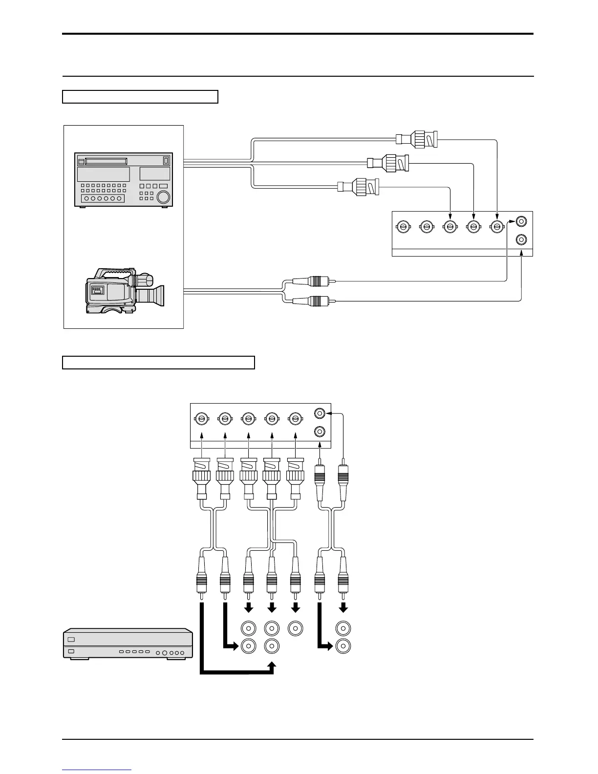
COMPONENT signal Connection
VD HD P
R
/C
R
/R P
B
/C
B
/B Y/G
L
R
COMPONENT/RGB IN
Video input to
Y, P
B
, P
R
sockets
Audio input to
L/R sockets
AUDIO
2×RCA Audio cables
3 × BNC
cables
Example of input signal source
HDTV-compatible VCR
or
RGB camera
AUDIO
The TUNER input terminal is reserved for use with future external compatible components.
2×RCA
Audio
cables
3×BNC
Video
cables
Example of input signal source
TUNER TU-PTA300B
VD HD PR/CR/R PB/CB/B Y/G
L
R
COMPONENT/RGB IN
AUDIO
RGB L
HD VD R
RGB signal (R, G, B, HD, VD) Connection
How to connect the COMPONENT/RGB Input Terminals
Connections
Notes:
(1) Change the “Component/RGB in” setting in the “Setup” menu to “RGB”. (see page 28, 30)
(2) Additional equipment and cables shown are not supplied with this set.
 Loading...