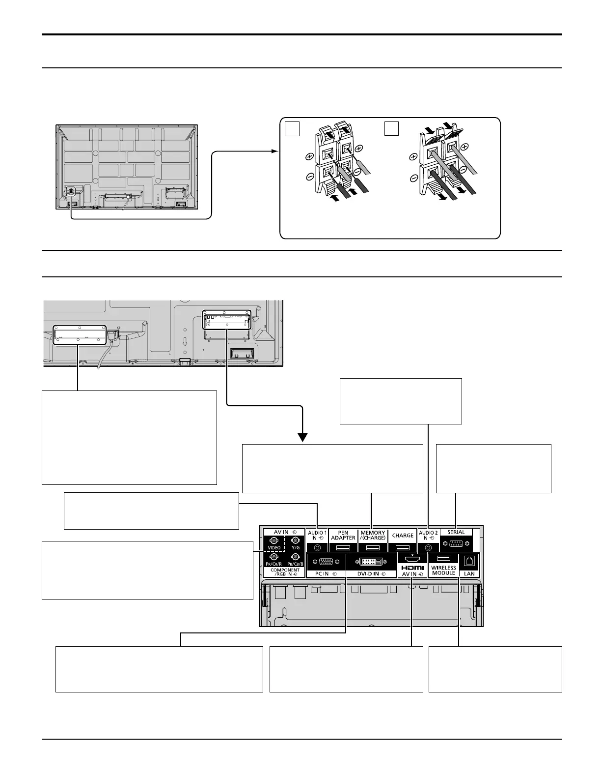
Video equipment connection
1
2
10
Connections
PEN ADAPTER, MEMORY/(CHARGE),
CHARGE:
Refer to “Operating Instructions,
Electronic Pen Operations”.
AUDIO 1 IN: Audio input
terminal shared with VIDEO and
COMPONENT/RGB IN. (see page 11)
DVI-D IN: DVI-D Input Terminal (see page 12)
PC IN: PC Input Terminal Connect to video
terminal of PC or equipment with Y,
PB(CB) and PR(CR) output. (see page 13)
AV IN (HDMI):
HDMI Input Terminal (see page 12)
Connect to video equipment such
as VCR or DVD player.
WIRELESS MODULE, LAN:
Refer to “Operating
Instructions, Network
Operations”.
AUDIO 2 IN:
Audio input terminal shared
with DVI-D IN and PC IN.
(see page 12, 13)
SERIAL:
Control the Plasma Display
by connecting to PC.
(see page 14)
AV IN (VIDEO): Composite Video Input Terminal
(see page 11)
COMPONENT/RGB IN: Component/RGB
Video Input Terminal
(see page 11)
For TH-65PB2U
Please use 8 Ω/10 W speaker.
Ex. TH-65PB2U
Speaker connection
Red
(L)
(L)
(R)
(R)
Black
While pressing the lever,
insert the core wire.
Red
Black
Return the lever.
For TH-50PB2U
Please use 6 Ω/8 W speaker.
Terminals are on the bottom side of the Plasma
Display.
SLOT: Terminal board (optional
accessories) insert slot
(see page 6)
Note:
The right side slot is for terminal board
with 2-slot width. The terminal board
with 1-slot width does not function
when installed in the right side slot.