13
0
1
2
345
6
1/2 1/2 1/2 1/2 1/2 1/2
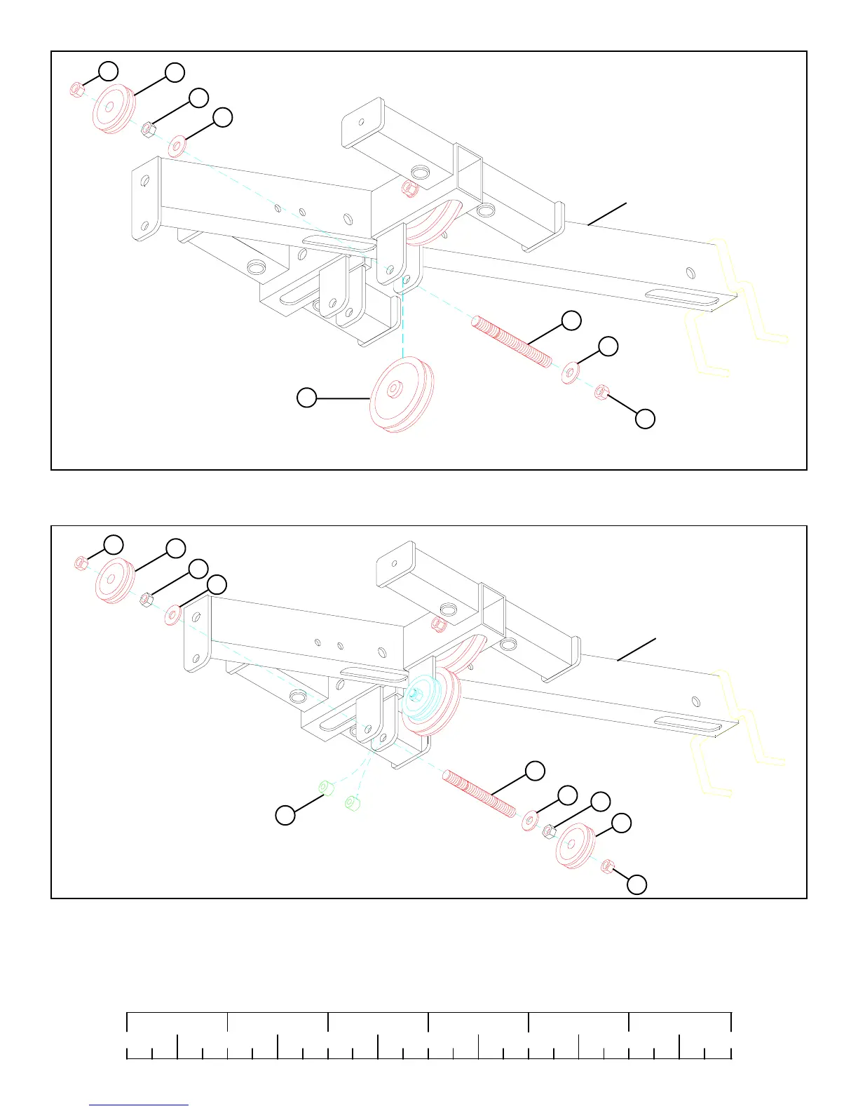
FIGURE 10
STEP 10
• Position two 3/8 X 1/2” SPACERS (109) inside the rear bracket of the TOP BOOM and slide one 3/8” THREAD SHAFT (106) through
the bracket. See FIGURE 10.
• SECURELY assemble two 2” PULLEYS (69) to the rear bracket on the TOP BOOM using the 3/8” THREADED SHAFT (106), two 3/8”
WASHERS (91), two 3/8” HEX NUTS (108), and two 3/8” LOCK NUTS (92) as shown in FIGURE 10.
109
92
91
91
42
FIGURE 9
STEP 8
• SECURELY assemble one 3-1/2” PULLEY (42) to the bracket on the TOP BOOM using one 3/8” THREADED SHAFT (106) , two 3/8”
WASHERS (91), one 2” PULLEY (69), one 3/8” HEX NUT (108) and two 3/8” LOCK NUTS (92). See FIGURE 9.
TOP BOOM
106
108 3/8” HEX NUT
69
92
108
92
91
91
TOP BOOM
106
108 3/8” HEX NUT
69
92
108
108 3/8” HEX NUT
108
69