NVX80 Version 1.02 11
Outputs and Wall Tamper In (Input)
Power Up
The NVX80 has 3 outputs and 1 input, called Wall Tamper In. The outputs menu also controls zones to 4 in the
Digiplex communication. The outputs can be used to define the relay functionality, and the input is used to control
the tamper input settings.
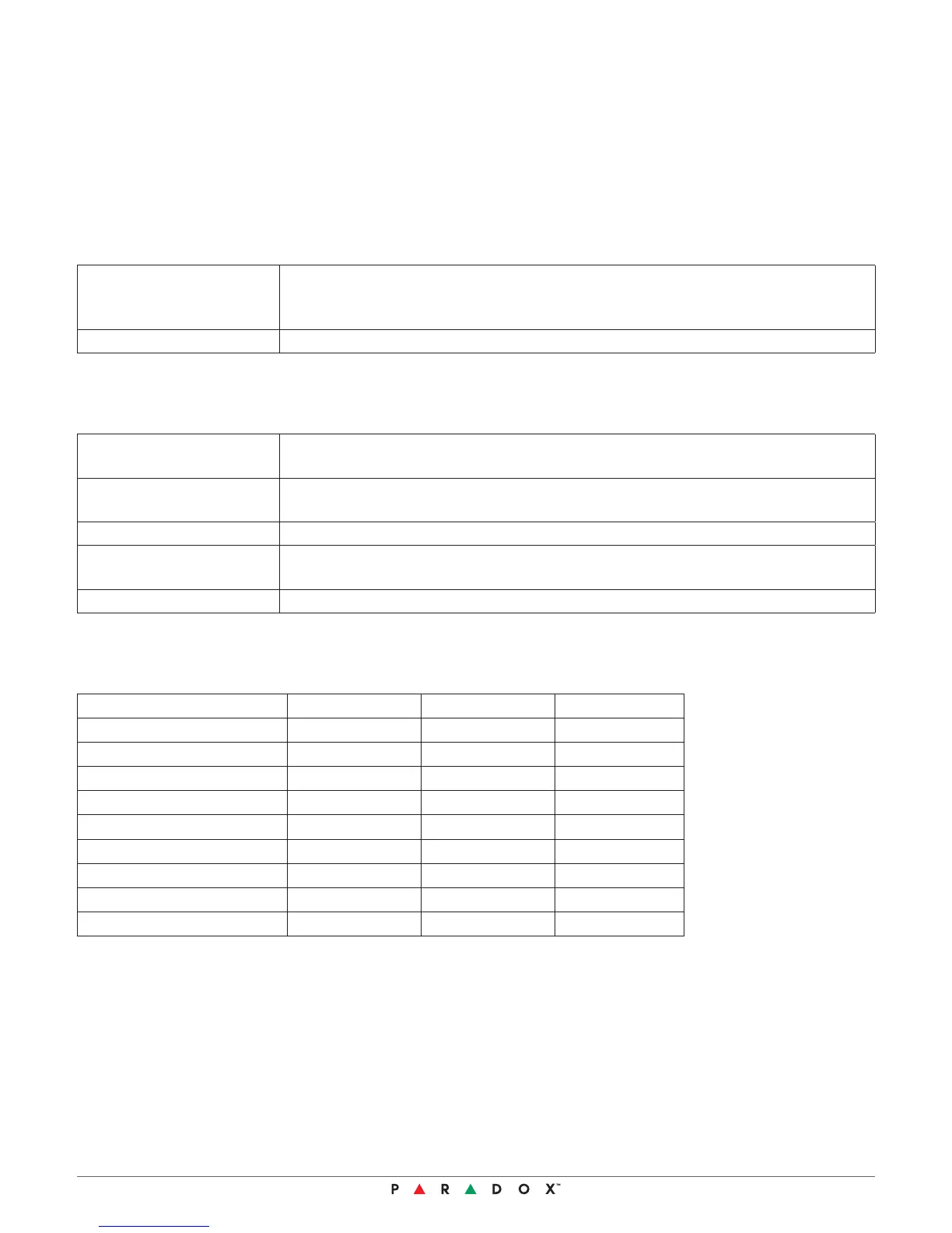
Wall Tamper In
Tamper Input Choose this option to receive TAMPER events from the wall tamper switch.
Install the wall tamper switch and wire it to between the BLK and TMP inputs on
the terminal connector.
Disable Disable events from the tamper terminal input.
Outputs Menu
Relay 1 Function Form C relay / N.C. and N.O. terminal outputs
Select events from a list to activate this relay
Relay 2 Function Relay 2 is a solid state relay
Select events from a list to activate this relay
Relay 2 Logic Select N.C. or N.O. (Remember: Relay 2 will open when power is lost)
Relay 3 Function Relay 3 is a solid state relay
Select events from a list to activate this relay
Relay 3 Logic Select N.C. or N.O. (Remember: Relay 3 will open when power is lost)
Relay Defaults
Relay 1 Relay 2 Relay 3
Alarm
3
Tamper
3
Anti-Mask
3
MW Anti-Mask
PIR
Microwave
Clean Lens
3
Trouble
Creep Zone
When the detector is first powered, it will display the power up sequence which indicates the various self-
diagnostics it completes including; hardware, PIR, MW, Anti-mask, panel connection, bus voltage and tamper.
The power up sequence should take approximately 30 seconds. If the unit does not successfully complete the
power up sequence it displays a trouble icon signifying a potential problem with the installation.
 Loading...