Installation Steps
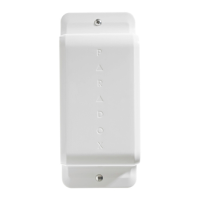
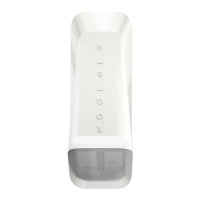
1. Loosen the tamper screw found at the bottom of the unit
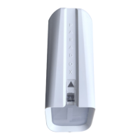
2. Separate the back cover from the unit by sliding the back of the unit down and off
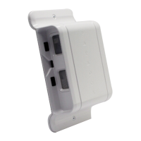
3. Drill or punch out the appropriate knock-out holes for either a wall or corner installation, refer to the
installation legend above
4. Make sure to allow for 20 mm / 0.78 in of space between the top of the unit and a ceiling or object found above it
5. Mark your selected location using the back cover of the unit as a template
6. Drill holes into the wall surface
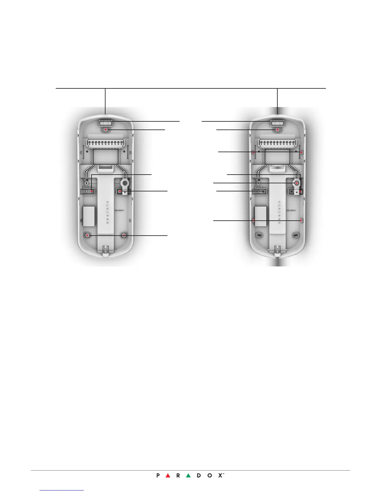
7. Thread the wires through the wire entry hole. To connect the Digiplex bus, attach the red, black, green and
yellows to their respective locations
8. Secure the back cover of the unit to the wall surface using mounting screws appropriate for
the specific installation
9. Slide the front section of the unit into place on the back cover of the unit. If the wires are connected to
electricity, then the power up sequence will automatically start
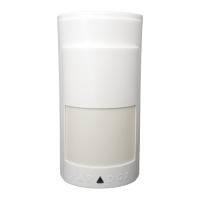
10. Ensure that the outer rim of the unit is tightly joined, so that waterproof casing is not compromised
11. While the tamper screw at the bottom of the unit is open, begin the power up process and access the menus
to change any sensitivity or other settings, then save the altered settings
12. Tightly close the tamper screw found at the bottom of unit and put the detector into operation mode
Legend
Wall Mount
Corner Mount
6 NVX80 Version 1.02
20 mm / 0.078 in minimum from the ceiling
Level
Wall Installation 1
Corner Installation 1
Corner Tamper Installation 1
Wall Installation 2
Wall Installation 3
Wiring Screw
Corner Installation 3
Installation
 Loading...