movethe controllerboard isthatsome
electronic components will be de
-
stroyediftheytouchagroundedobject
with the kiln plugged in. See chart,
page 22, for connection numbers on
back of board.
WARNING:Keepawayfromswitch
box opening when testing the
board. Switch box contains live
wires!
Problem: Controller Display
Does Not Light Up
Probable Causes:
■
Tripped Circuit Breaker or Blown Fuse,
Kiln Unplugged
■
Blown Kiln Switch Box Fuse
■
Defective Transformer
■
Defective Controller Board
■
Disconnected Switch Box Wire
Checkcircuitbreaker orfuseforthewall outlet.Ifpoweris
reaching the kiln, turn off the power for ten seconds. The
boardmaylightupwhenyouturnthepowerbackon.Ifitdoes
not, remove the kiln’s fuse. It
is located in the switch box.
Remove by pressing on the
fuseholderand turningcoun-
ter-clockwise half a turn.
Check the fuse by placing the
probesof anohmmeteron the
ends of the fuse. If the ohm-
meter reads less than an ohm
(digital meter) or reads 0 ohms (analog meter), the fuse is
okay.IfthereadingisOPEN(digitalmeter)orinfinity/nonee
-
dle movement (analog meter), the fuse is bad. Replacement
fuse:
AGC 1/2 A 250V AC
If replacement kiln fuses keep blowing, check the kiln’s
transformer.(Seebelowand“KilnSwitchBoxFuseBlowsRe
-
peatedly,” page 20, to check transformer.)
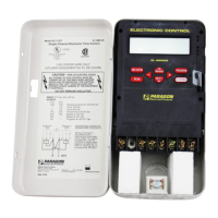
Next check the controller board with a voltmeter
multitester. Make sure kiln is unplugged, and remove the 4
screws holding the controller board faceplate to the switch
box.Liftfaceplateoutofboxandlettheboardhangonthebox
with the back of the board facing you. Plug the kiln back in.
Touch voltmeterprobes (inAC mode) toconnectors 5and 7.
Thisshouldbethewhiteandorangewires.(Seediagram,page
22.)
Make sure the voltmeteris in theAC modewhen placing
the probes on connectors 5 and 7.
Ifyoufindvoltage(at least20 voltsAC),itmeanscurrentis
reachingtheboardfromthetransformer,sotheboardisprob
-
ably defective. If there is no voltage, the transformer may be
defective. But before replacing the transformer, UNPLUG
kiln, remove switch box, and look for a disconnected wire be
-
tween the cord set and transformer or between the trans
-
former and controller board.
Problem: Controller Display Lights Up
Normally, Some or All Heating
Elements Do Not Fire
Probable Causes:
■
Worn or Burned Out Elements
■
Defective Controller Board
■
Defective Relay(s)
■
Disconnected Wire in Switch Box
■
Programmed Hold or Delay
Besureyouhave notinadvertently programmeda longDe
-
lay.Iffiringisexcessivelyslow,aHoldinRamp-Holdmayhave
been programmed. See “Element Glow Test,” page 15.
Checkthecontrollerboardwithavoltmeter.UNPLUGthe
kiln and remove the 4 screws holding the controller board
faceplatetotheswitchbox.Liftfaceplateoutofboxandletthe
boardhangontheoutsideoftheboxwiththebackoftheboard
facingyou.Then plugthe kilnbackin.Programthe controller
to fire to 1000°F at 9999°F rate in Ramp-Hold mode. Press
START.
Put the voltmeter in DC mode. (It must be in DC mode.)
Touch probes to connectors 3 and 6 for at least 12 seconds.
(See diagram, page 22.) If the meter reads 11 - 14 volts, the
board is sending correct voltage to the relays, so the board is
okay. Lessthan 11volts at 3and 6means aweak transformer.
No voltage at 3 and 6 means a defective controller board.
Ifthecontrollerboard checksout okay,UNPLUG kiln and
remove switch box. Look for loose or disconnected
board-to-relay, relay-to-element, and cordset-to-relay wires.
If you still haven’t found the
problem, check elements with
an ohmmeter.
Kiln is still UNPLUGGED.
If the elements are hot from
the previous test, please use
caution. Wait for the ele
-
ments to cool, if necessary.
Touch the ohmmeter leads
to the two element connectors
of each element. OPEN (digital
meter) or no-needle movement
(analog meter) indicates a bro
-
ken (burned out) element.
Iftheelementyouaretesting
has two or more element lead wires attached to thesame ele
-
mentconnector,youmusttemporarilydisconnectthosewires
fromtheconnector.Holdelementconnectorwithpliersasyou
remove the screw. Be gentle to avoid breaking the element.
(Elements are brittle after being fired.) Do not disturb the
screwholdingtheelement,onlytheoneholdingtheleadwires.
Reconnect the wires securely after testing the element.
If the elements and wiring check out okay, the problem is
most likely a relay.
16

 Loading...


