22
Board Upgrades
WARNING!Becarefultoattachthewirestothecor
-
rect terminals. Reversing wires can burn up circuit
board components and the transformer. Damage
from miswiring is not covered by warranty!
Upgrading to the DTC 1000 Board
From the DTC 100 Series
1 UNPLUG kiln.
2 Remove the 4 corner screws holding the DTC
100C or DTC 100 faceplate to the switch box.
Lift out the faceplate.
3 Loosen screws along the terminal strip on the
backoftheboard.Removeallconnectingwires.
4 Cut off the wire connection terminals from the
wireends. (Exceptforthermocouple wires;they
attach to the DTC 1000 the same way as the
DTC 100 series.)
5 Strip1/4"ofinsulationfromtheendofeachwire.
(Insulation must be kept out of the connector
sleeve.) Crimp a
push-on connector
(furnished with re
-
placement board) to
the wires. If your
DTC 100 series kiln
has a green wire,
crimp it together with
the red wire. Also,
crimp the blue and
black wires together.
Use the type of crimping
tool shown in the photo
above. The indent goes on
the side opposite the seam
of the connector. Test each
connection by
grasping the
push-on connector
with one hand and
pulling the wire
firmly with the
other.
6 Connect wires
to board using the diagram below. Install DTC
1000 faceplate to the switch box.
Upgrading from DTC 600 &
DTC 800 Series
UNPLUG kiln and remove the 4 corner screws hold-
ing the board to the switch box. Lift out the faceplate.
Transferwiresfromyour boardto thenew board. Use
the color coding shown in the diagram. If your kiln used
the AOP output, the AOP wire attaches to terminal #1.
#13 Yellow
#12 Red
#11 Yellow
#10 Red
#9 Yellow
#8 Red
#1 AOP (Auxiliary Output)
Connect
thermocouple to
center screws #10
& 11.
Do not use #8,
#9, #12 and
#13.
#4 DO NOT USE
#5 White (Transformer)
(24vAC)
#6 Blue (Transformer) Black
(Relay) Crimp blue and black
wires together (Ground)
#7 Orange (Transformer)
(24vAC)
#2 DO NOT USE
#3 Red or Red & Green (Relay)
If your DTC 100 kiln has a
green wire, crimp red & green
together (+12vDC)
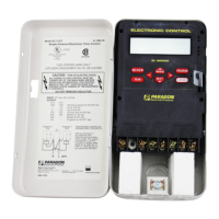
Back of DTC 1000
Board, Top
 Loading...