4-1 Operating the Converter
512C Series Converter
OPERATING THE CONVERTER
Pre-Installation Planning
Basic Wiring Diagrams
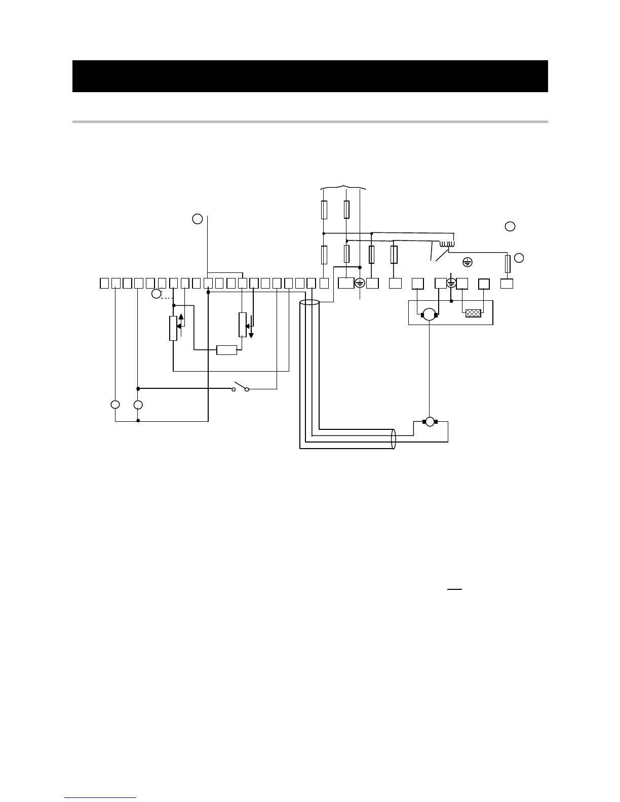
Basic Connection
L1 L2/N FL1 FL2
A+ A-
F+ F-
Aux
FS1 FS2
FS4
FS5
Tachogenerator
A utotr ansf or mer
Branch Protection (Fuses or Circuit Breaker)
1
1
Mains Supply
PE
GND
PE
GND
DC
Motor
Optional
1 3 4 5 6 7 8 9 10 11 12
14 15 16
19 23 13
10K
SPEED
RUN
10K
10K
100%
CURRENT
LIM IT
EXTERNAL
(Optio nal)
SETPOINT
Speed
Relay
Health
Relay
3
2
Signal Ground
standard
voltage
c
When the mains voltage is non-standard, i.e. not selectable via the transformer tapping link
(380/415V, 220/240V or 110/120V), connect a low power Autotransformer to generate a
standard voltage. Connect the output of the Autotransformer to the AUX terminal. Move the
Supply Selector from "MAINS" to "AUX". Select the appropriate voltage via the transformer
tapping link. The Autotransformer must be connected to the same phase as the incoming
power to provide correct coding to the controller.
d
It is recommended that the “0V/common” be connected to protective earth/ground for safety
reasons. In a system comprising of more than one controller, the “0V/common” signals
should be connected together and joined to protective earth/ground at one
point only.
e
Stall override link between terminals 14 and 15 required when using controller in current
control.
 Loading...
