6-2 Terminal Descriptions
512C Series Converter
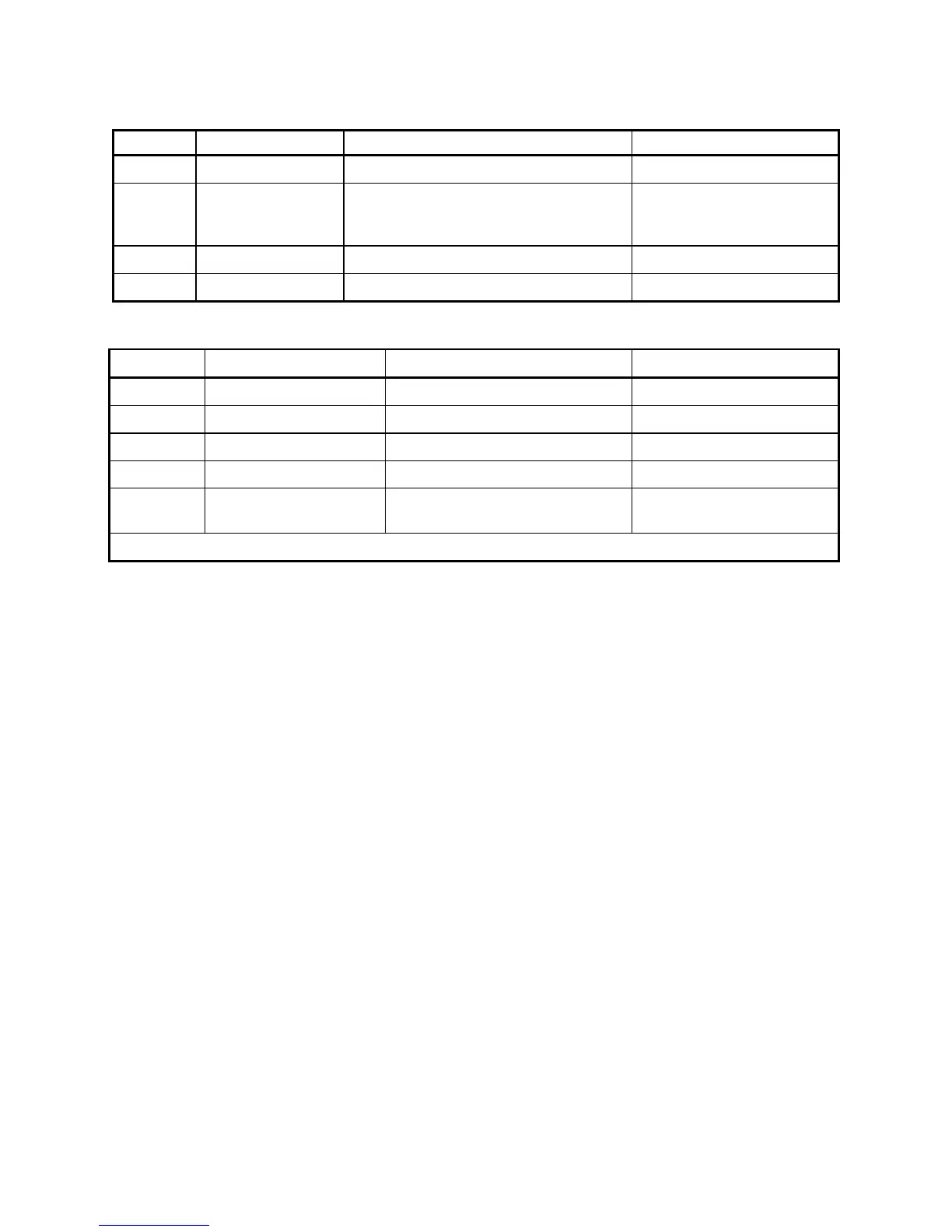
Power Terminals
TERMINAL FUNCTION DESCRIPTION NOTES
L1 AC Input Line 1 Mains Supply Line1 Input
L2/N AC Input Line2/
Neutral
Mains Supply Line2 Input or Neutral Must also be used as Auxiliary
Supply Return when Auxiliary
Supply Input used.
A+ Armature Positive Motor Armature Positive Output.
A- Armature Negative Motor Armature Negative Output.
Field Terminals (Auxiliary Supply)
TERMINAL FUNCTION DESCRIPTION NOTES
F+ Field Positive Motor Field positive DC Output
F- Field Negative Motor Field negative DC Output
FL1 Field Rectifier Supply Mains Supply Input Field Rectifier
FL2 Field Rectifier Supply Mains Supply Input Field Rectifier
* Aux L1 Auxiliary Supply Auxiliary Supply Input to Control
Transformer.
Auxiliary Supply Return via
L2/N
* The signal applied to Aux L1 must be in phase with L1 in order to provide the correct coding for the controller.
 Loading...
