4-22 Operating the Drive 590 Series DC Digital Drive
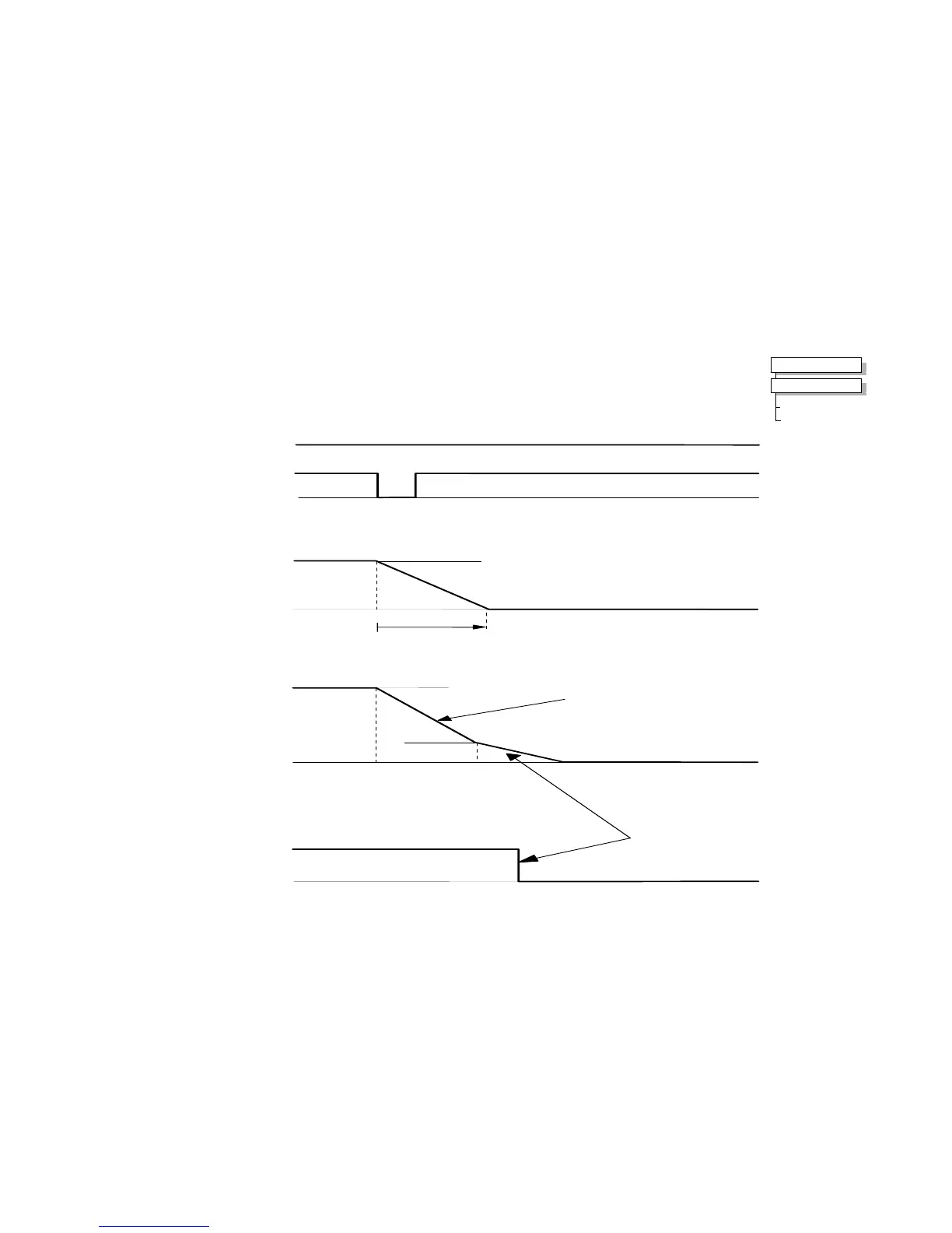
Program Stop (B8)
This is achieved by removing 24V from Terminal B8.
The motor speed is brought to zero under conditions defined by the PROG. STOP TIME (ramp rate) and PROG. STOP I
LIMIT parameters.
SPEED SETPOINT ( 100% )
PROGRAM STOP TIMING
PROGRAM STOP
LED
OFF
LED ON ( PROGRAM STOP FALSE )
(PROGRAM STOP IS A
LATCHED FUNCTION)
t
t
100% = SPEED SETPOINT
0%
0%
PROG STOP TIME
DEFAULT 0.1 SEC
SPEED DEMAND
= SPEED SETPOINT
CURRENT LIMIT SET BY
PROG STOP I LIMIT
( DEFAULT 100% )
ACTUAL STOPPING RATE DEPENDS
ON LOAD INERTIA, MOTOR HP AND
OVERLOAD CAPABILITY OF MOTOR/DRIVE
t
SPEED
(DEFAULT 2%)
0%
DRIVE RUN LED
0%
DRIVE ENABLE =ENABLED
DRIVE ENABLE =DISABLED
t
AND CONTACTOR
TURNS OFF BELOW
DRIVE RUN LED AND START CONTACTOR
STOP ZERO
SPEED FEEDBACK
DRIVE IS DISABLED
STOP ZERO SPEED
Control Signals
Speed Demand
Actual Speed
Indicators
AND START CONTACTOR
MMI Menu Ma

 Loading...


