Pilot Operated Prop. DC Valve with VCD
®
Series D*1FP/FE Explosion Proof
Operation Manual
17
Parker Hannifin Corporation
MSG11-5715-718 D_1FP IECEX UK.indd 19.12.19
1)
Diagnostic signal 12,5 V in error case. Spool moves in a dened
postion, please see ordering code "spool position at power down".
Enable input
A signal voltage enables the actuator drive of the
valve. Continuous operation of the valve requires
a permanent voltage 5...30 V (e.g. the supply volt-
age). In case of disabling the signal the valve will
reach its power down position spring-actuated
independently from the command signal value.
The enable function represents no safety
arrangement against unwanted valve opera-
tion in terms of accident prevention regula-
tions.
Command signal input
The spool stroke is proportional to the command
signal amplitude. Details are disclosed in the
technical data.
The command input signal needs to be ltered
as well as free of inductive surges and
modulations. Due to the sensitivity of the
valve a high signal quality is recommended.
This will prevent malfunction.
The option 4...20 mA uses the “< 3.6 mA“
condition as breakdown-information. If the
input signal line is interrupted, an evaluable
failure information is available. In this case
the actuator drive will be switched off. The
drive will switch on when the input signal
reaches a value of 3.8 mA, it switches off
when the command falls below 3.6 mA. This
determination follows the NAMUR-speci-
cation NE43.
NAMUR is an association of users of process
control technology.
Diagnostic output
A diagnostic signal is available. Its voltage repre-
sents the operating condition of the valve.
The output may drive a load of max. 5 mA.
Exceeding of this limit leads to malfunction.
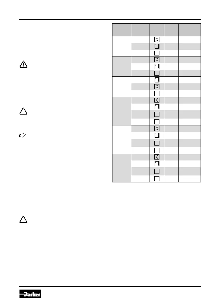
Code
command
signal
Command
signal
Func-
tion
VCD ac-
tuator
Diagnostic
signal
B
0…+10 V on 0…-10 V
0…-10 V on 0…+10 V
Overload
aus 12.5 V
E
0…+20 mA on 0…-10 V
0…-20 mA on 0…+10 V
Overload off 12.5 V
K
0…+10 V on 0…+10 V
0…-10 V on 0…-10 V
Overload off 12.5 V
L
0…-20 mA on 0…-10 V
0…+20 mA on 0…+10 V
0…3.6 mA off
Cable break,
12.5 V
Overload off 12.5 V
R
12...20 mA on 0…-10 V
12…4 mA on 0…+10 V
0…3.6 mA off
Cable break,
12.5 V
Overload off 12.5 V
S
4…12 mA on 0…-10 V
12…20 mA on 0…+10 V
0…3.6 mA off
Cable break,
12.5 V
Overload off 12.5 V
1)
1)
1)
1)
1)
1)
1)
1)
1)

 Loading...


