26
Pilot Operated Prop. DC Valve with VCD
®
Series D*1FP/FE Explosion Proof
Operation Manual
Parker Hannifin Corporation
MSG11-5715-718 D_1FP IECEX UK.indd 19.12.19
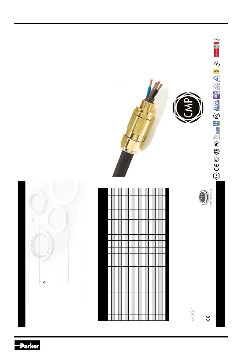
ASSEMBLY FITTING INSTRUCTIONS
FOR INSTALLATION OF CMP CABLE
GLAND TYPES T3CDS & T3CDSPB
CABLE GLAND FOR USE WITH SINGLE WIRE ARMOUR (SWA), WIRE BRAID, STRIP, AND TAPE ARMOUR
(T3CDSPB VERSION CAN ALSO BE USED ON CABLE WITH A LEAD SHEATH).
FOR USE IN HAZARDOUS LOCATIONS.
INCORPORATING EC DECLARATION OF CONFORMITY TO DIRECTIVE 94/9/EC
CMP TRITON
TM
CDS
TM
DELUGE PROOF CABLE GLAND FEATURING
COMPENSATING DISPLACEMENT SEAL SYSTEM.
CMP Document No. FI408 Issue 2 09/10
0518
Glasshouse Street • St. Peters • Newcastle upon Tyne • NE6 1BS
Tel: +44 191 265 7411 • Fax: +44 191 265 0581
E-Mail: cmp@cmp-products.co.uk • Web: www.cmp-products.com
Notified Body: Sira Certification Service, Rake Lane, Chester CH4 9JN, England.
I, the undersigned, hereby declare that the equipment referred to herein conforms to 94/9/EC directive.
Dr Geof Mood - Technical Director - (Authorised Person)
DUBAI • HOUSTON • NEWCASTLE • SINGAPORE • SHANGHAI • PUSAN • PERTH
www.cmp-products.com
Cable Gland Selection Table
CMP PRODUCTS
Logo’s shown for illustration purposes only. Please check certification for details
TECHNICAL DATA
CABLE GLAND TYPE : T3CDS / T3CDSPB
INGRESS PROTECTION : IP66, NEMA 4X, DELUGE TO DTS01-01, Oil Resistance II
PROCESS CONTROL SYSTEM : BS EN ISO 9001
HAZARDOUS AREA CLASSIFICATION
ATEX CERTIFICATION No : SIRA 06ATEX1283X & SIRA 06ATEX4328X
ATEX CERTIFICATION CODE : II 2 GD Ex d IIC / Ex e II / Ex nR II / Ex tD A21 IP66
IEC Ex CERTIFICATION No : IEC Ex SIR.07.0005X
IEC Ex CERTIFICATION CODE : Ex d IIC / Ex e II / Ex nR II / Ex tD A21 IP66
CSA-US CERTIFICATION No : CSA.02.310517X
C
SA-US CERTIFICATION CODE : Class I, Div 2, Groups ABCD; Class II, Div 2, Groups EFG; Class III; Ex d IIC; Ex e II;
Class I, Zone 1, AEx d IIC; Class I, Zone 1, AEx e II
INSTALLATION INSTRUCTIONS
Installation should only be performed by a competent person using the correct tools. Read all instructions before beginning installation.
SPECIAL CONDITIONS FOR SAFE USE
1. The glands ranges shall only be used on enclosures where the temperature, at the point of mounting, is in the range -6
0°C to +130°C.
2. When used with braided cable, the cable glands shall be used for fixed installations only. Cables must be effectively clamped to prevent twisting
and pulling.
3. When used in Group I applications, the equipment must only be mounted where the risk of mechanical impact is low.
4. According to CEC Wiring methods, connectors with Metric entry threads are only suitable for Areas classified in ZONES unless fitted with an
approved Metric to NPT thread conversion adaptor.
ACCESSORIES
The following accessories are available from CMP Products, as optional extras, to assist with fixing, sealing and earthing :-
Locknut | Earth Tag | Serrated Washer | Entry Thread (I.P.) Sealing Washer | Shroud *
** Insert “PB” into the code for T3CDSPB glands e.g. 20T3CDSPB1RA
* For IP67 & IP68 requirements the Cable Diameter “B” (minimum value) shown above should be increased by 1.0 mm to ensure complete compliance
CABLE GLAND
CABLE GLAND
TYPES T3CDS
TYPES T3CDS
& T3CDSPB
& T3CDSPB
Cable
Gland
Size
Available Entry Threads
Minimum
Thread
Length
Cable
Bedding
Diameter
Overall
Cable
Diameter
Armour Range +
Across
Flats
Across
Corners
Protrusion
Length
Ordering
Reference
(Brass Metric)
#
Cable
Gland
Weight
(Kgs)
Standard Option Grooved Cone Stepped Cone
Metric NPT NPT Min Max Min Max Min Max Min Max Max Max
20S/16 M20 1/2" 3/4" 15.0 3.2 8.7 6.1 13.4 0.15 1.0 0.9 1.0 24.0 25.9 70.0 20S16T3CDS1RA 0.170
20S M20 1/2" 3/4" 15.0 6.1 11.7 9.5 15.9 0.15 1.0 0.9 1.25 24.0 25.9 70.0 20ST3CDS1RA 0.170
20 M20 1/2" 3/4" 15.0 6.5 14.0 12.5 20.9 0.15 1.0 0.9 1.25 30.5 32.9 72.0 20T3CDS1RA 0.256
25S M25 3/4" 1" 15.0 11.1 20.0 14.0 22.0 0.15 1.0 1.25 1.6 37.5 40.5 82.0 25ST3CDS1RA 0.384
25 M25 3/4" 1" 15.0 11.1 20.0 18.2 26.2 0.15 1.0 1.25 1.6 37.5 40.5 82.0 25T3CDS1RA 0.379
32 M32 1" 1 1/4" 15.0 17.0 26.3 23.7 33.9 0.15 1.0 1.6 2.0 46.0 49.7 85.0 32T3CDS1RA 0.560
40 M40 1 1/4" 1 1/2" 15.0 23.5 32.2 27.9 40.4 0.15 1.0 1.6 2.0 55.0 59.4 86.0 40T3CDS1RA 0.848
50S M50 1 1/2" 2" 15.0 31.0 38.2 35.2 46.7 0.15 1.0 2.0 2.5 60.0 64.8 98.0 50ST3CDS1RA 1.055
50 M50 2" 2 1/2" 15.0 35.6 44.1 40.4 53.1 0.15 1.0 2.0 2.5 70.0 75.6 100.0 50T3CDS1RA 1.521
63S M63 2" 2 1/2" 15.0 41.5 50.0 45.6 59.4 0.15 1.0 2.0 2.5 75.0 81.0 108.0 63ST3CDS1RA 1.750
63 M63 2 1/2" 3" 15.0 47.2 56.0 54.6 65.9 0.15 1.0 2.0 2.5 80.0 86.4 103.0 63T3CDS1RA 1.685
75S M75 2 1/2" 3" 15.0 54.0 62.0 59.0 72.1 0.15 1.0 2.0 2.5 89.0 96.1 105.0 75ST3CDS1RA 2.345
75 M75 3" 3 1/2" 15.0 61.1 68.0 66.7 78.5 0.15 1.0 2.0 2.5 99.0 106.9 114.0 75T3CDS1RA 3.200
90 M90 3" 3 1/2" 15.0 66.6 79.3 76.2 90.4 0.25 1.6 3.15 3.15 114.0 123.1 140.0 90T3CDS1RA 5.100
100 M100 4" 4 1/2" 15.0 76.0 91.0 86.1 101.5 0.25 1.6 3.15 4.0 123.0 132.8 170.0 100T3CDS1RA 6.500
115 M115 4 1/2" 5" 15.0 86.0 98.0 101.5 110.3 0.25 1.6 3.15 4.0 133.4 144.1 210.0 115T3CDS1RA 7.000
130 M130 5" 6" 15.0 97.0 115.0 114.2 123.3 0.25 1.6 3.15 4.0 146.1 157.8 250.0 130T3CDS1RA 7.800
Dimensions are displayed in millimetres unless otherwise stated
A2. Cable glands

 Loading...


