Pilot Operated Prop. DC Valve with VCD
®
Series D*1FP/FE Explosion Proof
Operation Manual
27
Parker Hannifin Corporation
MSG11-5715-718 D_1FP IECEX UK.indd 19.12.19
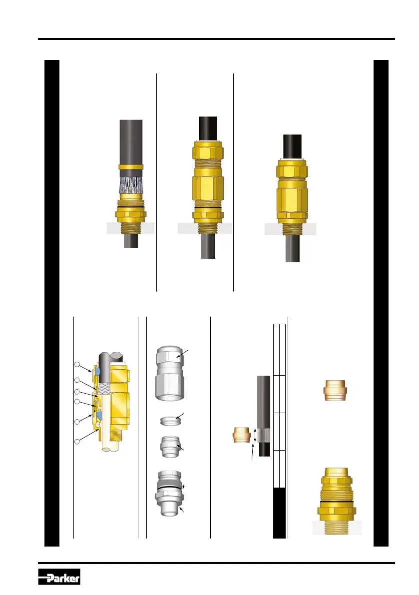
INSTALLATION INSTRUCTIONS FOR CMP CABLE GLAND T3CDS & T3CDSPB
DUBAI • HOUSTON • NEWCASTLE • SINGAPORE • SHANGHAI • PUSAN • PERTH
DUBAI • HOUSTON • NEWCASTLE • SINGAPORE • SHANGHAI • PUSAN • PERTH
www.cmp-products.com
www.cmp-products.com
CABLE GLAND COMPONENTS
PLEASE READ ALL INSTRUCTIONS CAREFULLY BEFORE BEGINNING THE INSTALLATION
1. Separate the gland into two sub-assemblies, A and B, by unscrewing the body (2) from the entry
item (1). Note that items (4) and (5) are loose items.
2. Prepare the cable by stripping back the cable outer sheath and armour to suit the equipment
geometry. Expose the armour by stripping back the outer sheath further using the table below as a
guide.
3. Secure the entry components (sub-assembly A) into the equipment. (Not for remote installation)
Pass the sub-assembly B and AnyW
ay clamping ring (5) over the cable, outer seal first.
Insert the reversible armour cone (4) in the sub-assembly B, orientated correctly:
4. Pass the cable through sub-assembly A, spacing the armour or braid evenly around the cone.
Whilst continuing to push the cable forward to keep the cable braid or armour in contact with the
cone, tighten the compensating sleeve (3) into the entry component (1) until all the threads are
used. (Note that the internal compensator will prevent the cable gland inner seal from being over-
tightened onto the cable inner sheath.)
The inner sheath of the T3CDSPB gland contains a devi
ce to automatically make an electrical
contact with the lead sheath on the cable as the cable is installed.
5. Terminate the cable by tightening the body (2) onto the entry component (1) using a spanner on
each part. Tighten the body until the body and entry components are metal to metal and cannot
be tightened further.
6. Tighten the outer seal nut (6) until it comes to an effective stop. This will occur when:-
A) The outer seal nut (6) has clearly engaged the cable and cannot be fur
ther tightened
without the use of excessive force by the installer.
B) The outer seal nut (6) is metal to metal with the body of the gland (2).
4321
1. Entry Item
2. Body
3. Compensating Sleeve
4. Reversible Armour Cone
5. AnyWay Clamping Ring
6. Outer Seal Nut
65
SUB-ASSEMBLY A
ITEM 4 ITEM 5 SUB-ASSEMBLY B
“CDS” INNER SEAL
HOUSING
DELUGE
SEAL
REVERSIBLE
ARMOUR CONE
ANYWAY
CLAMPING RING
BODY AND OUTER
SEAL NUT
CABLE GLAND SIZE 20S/16, 20S, 20 25S, 25, 32, 40 50S, 50, 63S, 63 75S, 75, 90, 100, 115, 130
CABLE STRIP LENGTH “L” 12mm 15mm 18mm 20mm
Cable Strip
Length “L”
Grooved side of cone
outwards - to
terminate braid, strip
armour, pliable wire
or tape armour.
Stepped side of cone
outwards - to
terminate SWA cable.

 Loading...


